Settings
39
Pos: 18.4 /Überschri ften/Überschri ften 2/A-E/EEntlastung sfeder(n) @ 2\mod_120350 8983876_78.doc x @ 66384 @ 2 @ 1
8.1 Compensation Spring(s)
Pos: 18.5 /BA/Sic herheit/7. Gefahrenhin weise alt/Mähwerke/ Gefahr - Einstellung an den En tlastungsfeder n @ 0\mod_1196751594562_78. docx @ 12575 @ @ 1
Danger! - Setting on the compensation springs
Effect: Danger to life or serious injuries
• The compensation springs must only be removed in transport position. In the working
position the compensation springs are subject to high tensile stress.
• Severe injury can be caused if the compensation springs are removed while in the working
position.
• The lower threaded blocks on the compensation springs must be fully screwed in.
Pos: 18.6 /BA/Einste llungen/Mähwerke/Easy Cut/Entlastungsf eder(n)/Entla stungsfedern am Traktor einstellen Bild EC 28/3 2 @ 10\mod_12217375021 92_78.docx @ 136861 @ @ 1
AFA-1-00
4
3
1
2
a
5
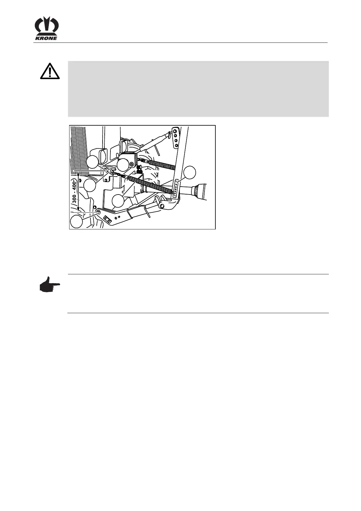
Fig. 21
Pos: 18.7 /BA/Einste llungen/Mähwerke/Easy Cut/Entlastungsf eder(n)/Entla stungsfedern am Traktor einstellen Text EC 28/32 28/ 32 CV @ 10\mod_122173719 0442_78.docx @ 136798 @ @ 1
• Bring the front mowing unit into the transport position
• Hook compensation spring (3) onto perforated bar (4).
• Attach with holder (2) on support point "a" and secure with hinged cotter pin (1)
Pos: 18.8 /BA/Einste llungen/Mähwerke/Easy Cut/Entlastungsf eder(n)/Ei nstellen der Entlastungsf edern am Traktor Maß 300-400 Hinweis @ 10\mod_1221737 438036_78.doc x @ 136841 @ @ 1
Note
Setting dimension of the compensation springs
Effect: Proper use of the machine.
The distance between support point "a" of the compensation spring (3) and the pivot point of
the tractor's lower suspension arms (5) should be between 300 – 400 mm.
Pos: 18.9 /Layout Module /---------------Seitenumbruch---------------- @ 0\mod_119617531122 6_0.docx @ 4165 @ @ 1
 Loading...