6. CYLINDER HEAD/VALVES
6-2
DINK 200i/125
SERVICE INFORMATION
GENERAL INSTRUCTIONS
The cylinder head can be serviced with the engine installed in the frame. Coolant in the radiator
and water jacket must be drained first.
When assembling, apply molybdenum disulfide grease or engine oil to the valve guide movable
parts and valve arm sliding surfaces for initial lubrication.
The valve rocker arms are lubricated by engine oil through the cylinder head engine oil passages.
Clean and unclog the oil passages before assembling the cylinder head.
After disassembly, clean the removed parts and dry them with compressed air before inspection.
After removal, mark and arrange the removed parts in order. When assembling, install them in
the reverse order of removal.
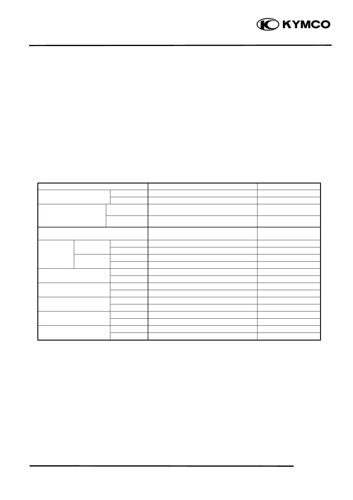
SPECIFICATIONS
Unit: mm (in)
Ite
DINK 200i 16 kg/cm²(1600 kpa, 227.2 psi) !
Cylinder head
compression pressure
DINK 125 15 kg/cm²(1500 kpa, 213 psi) !
Cylinder head warpage ! 0.05 (0.002)
IN 31.2365
Valve rocker arm I.D.
EX 10Д10.018
Valve rocker arm shaft IN 9.972Д9.987
Valve stem O.D.
EX 4.97Д4.955
Valve guide I.D.
EX 5Д5.012
TORQUE VALUES
Cylinder head cover bolt 1.2 kgf-m (12 N-m, 8.6 lbf-ft)
Tensioner mounting bolt 0.9 kgf-m (9 N-m, 6.5 lbf-ft)
Tensioner sealing bolt 0.9 kgf-m (9 N-m, 6.5 lbf-ft)
Cylinder head cap nut (DINK 200i) 2.3 kgf-m (23 N-m, 16.6 lbf-ft)
Apply engine oil to threads
Cylinder head cap nut (DINK 125) 2 kgf-m (20 N-m, 14.4 lbf-ft)
Apply engine oil to threads
Cylinder head bolt 1 kgf-m (10 N-m, 7.2 lbf-ft)
Valve clearance (cold)
 Loading...