Home
Lamtec
Control Systems
UI400
Lamtec UI400 User Manual
4
of 1
of 1 rating
284 pages
Give review
Manual
Specs
To Next Page
To Next Page
To Previous Page
To Previous Page
Loading...
177
7
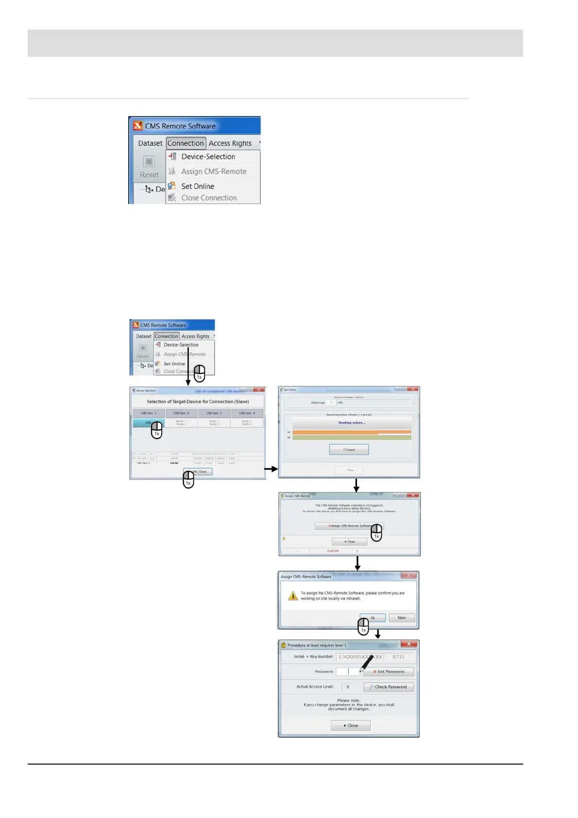
Operating Control and Displays
7.3.3.2
Connection Menu
Fig. 7-51 CMS connection menu
The "Connection" menu path can be used to:
•
Make a device selection
•
Assign CMS-Remote
•
Establish a connection (set online)
•
Drop a connection
Device selection
Fig. 7-52 CMS device selection menu
177
179
Table of Contents
Default Chapter
3
Table of Contents
3
1 Important Information about the Manual
11
Abbreviations
11
2 Safety
13
Classification of the Safety Instructions and Warnings
13
Target Group
14
Product-Specific Dangers
14
Mounting Notes
16
Installation Notes
17
Commissioning Notes
18
Electronic Ratio Control
18
Basic Device
19
Parameter Settings
19
Ffs/Ion/Terminal - Flame Tolerance Time
19
Electrical Connection Flame Sensor
20
CO/O 2 Measuring Systems
21
Acceptance and Inspection
21
Components/Devices of External Manufacturers
22
3 System Description
23
Brief Description
23
Digital Input/Output Functions
25
Digital Inputs
25
Digital Outputs
27
Assignment of Input/Output Functions
27
Chain Functions
28
Curve Set Selection
28
Analogue Inputs/Outputs
28
Analogue Inputs
28
Analogue Outputs
28
Functional Description of the Modules
29
Life Cycle
30
4 CMS Components
31
MCC - Master Control Component (Burner Module)
31
For Your Safety
31
Technical Data
31
Functional Description
33
Leds
34
Terminal Assignment
35
Connection Diagram
36
Interfaces
37
AEC-TPS - Actuator Extension Component Three-Point Step
38
Technical Data
38
Functional Description
40
Leds
41
Connection Diagram
43
Interfaces
43
For Your Safety
51
Leds
55
Interfaces
56
Connection Diagram
56
SDO - Safe Digital Output
57
For Your Safety
57
Technical Data
57
Terminal Assignment
59
Functional Description
60
Leds
60
Connection Diagram
61
Interfaces
61
SAI - Safe Analogue Input
62
For Your Safety
62
Technical Data
62
Terminal Assignment
64
Functional Description
64
Leds
65
Connection Diagram
66
Interfaces
69
UI400 - User Interface
70
For Your Safety
70
Technical Data
70
Functional Description
71
Pin Assignment
71
Interfaces
72
Graphic User Interface - GUI607/GUI610/GUI615
72
For Your Safety
72
Technical Data
72
Gui607
72
Gui615
75
Connection Diagram
77
Interfaces
78
Router
79
For Your Safety
79
Functional Description
79
5 Functional Description with Process Diagrams
80
Basic Burner Sequencer Functionality
80
Default Process Flow for Gas Modulating with Pilot Burner
80
Default Process Flow for Gas Modulating Without Pilot Burner
82
Default Process Flow for Oil Modulating with Pilot Burner
83
Default Process Flow for Oil Modulating Without Pilot Burner
85
Additional Burner Sequencer Functionality
86
Start Without Pre-Purge
86
Requirements
86
Required Inputs/Outputs
86
Required Parameters
86
Functional Description
86
Standby Mode
87
Requirements
87
Required Inputs/Outputs
87
Required Parameters
87
Functional Description
88
Purging the Fuel Train
89
Requirements
89
Required Inputs/Outputs
89
Required Parameters
90
Purging with Digital Input
92
Burner
92
Operating Modes for the 'Purging Fuel Train Function
93
Pilot Burner - Continuous Operation
93
Requirements
93
Required Inputs/Outputs
93
Required Parameters
94
Process Sequence Chart: Pilot Burner Continuous Operation
94
CPI/POC - Closed Position Indication/Proof of Closure
95
Requirements
95
Required Inputs/Outputs
95
Required Parameters
95
Functional Description
95
Valve Leakage Test
96
Requirements
96
Required Parameters
96
Functional Description
97
Valve Leakage Test Flow Chart
98
Process Sequence Chart
99
Calculation Example
99
Suggested Circuit for Venting
101
Electronic Ratio Control System
102
Requirements
102
Required Inputs/Outputs
102
Required Parameters
102
Commissioning
102
Physical Actuator Types
102
Continuous Actuators
102
Actuators with TPS Control
103
Logical Actuator Channels
103
Burner Firing Rate Controller
104
Requirements
104
Required Inputs/Outputs
104
Required Parameters
104
Configuration
104
I Term
105
Constant Controller
105
Controlled by Atmospheric Conditions
106
Limiting the Firing Rate Controller
106
Burner Shut-OFF
107
Functional Description
108
SPS Parameters
108
6 Commissioning
109
Parameter and Password Input
109
Commissioning Tests
109
Programming of Curves
109
Programming Curves
110
Configuring Special Points
112
Configuring the Range Limits
113
Shut-Off Limits
114
Run to Shut-Off Limits
114
Checking the Shut-OFF Limits of the CMS with the CMS Remote Software
114
Checking the O2 Effect
116
7 Operating Control and Displays
117
Operation, Controls and Display with UI400
117
Menu Functions
117
Main Menu
119
Information Menu Path
119
Burner Details
120
Recalling Fault History
121
Software Version
122
Display of Check Sums
123
Positions of Actuators
123
Display IP Address
123
Manual Menu Path
124
Settings Menu Path
125
Password
125
Program Sequence
126
Configuring the Servomotors
129
Deleting Curves
131
Adjusting Controller
132
Changing Password
133
UI400 Settings
133
Operation, Controls and Display with GUI607/610/615
134
Process Diagram and Menu Navigation
135
Password
138
Burner Settings Menu
139
Burner Firing-Rate Controller Menu
149
CO/O2 Burner Optimisation Menu
153
Flame Monitoring System Menu
155
System Functions Menu
156
User Settings
163
Operation, Controls and Display with CMS Remote Software
165
Remote Software
165
Installation Prerequisites
165
Installing the Software
165
Offline/Online
168
Offline Mode
168
Online Mode
169
Connecting the CMS to the PC
169
CMS Remote Software User Interface
173
Dataset Menu
174
Connection Menu
178
Access Rights Menu
179
CMS Menu
182
Options Menu
203
Help Menu
207
8 CO/O 2 Control
208
For Your Safety
208
Safety Concept
208
Requirements
209
Required Inputs/Outputs
209
Required Parameters
209
Why Control CO
210
Where Can CO Control be Used
210
Overview of Functions
211
Optimisation Strategy
212
Advantages of CO Control over O Trim
212
Operating Control and Displays
212
Is CO Control or O2 Trim Activated
212
Display in the Case of Active CO/O2 Control
214
Display with Active CO Control
214
Display for Active O Trim
214
Status Display in Case of O2 Trim
214
Resetting Faults
215
Electrical Connection - Connection Via LSB
215
Electrical Connection
215
Lamtec System Bus (Lsb)
215
Settings
216
Activating CO/O2 Control
216
Access Levels
216
Password Entry
217
Installation and Commissioning
217
Guidelines for Commissioning CO/O2 Controller
217
Putting the Electronic Ratio Control System into Operation
218
Combined O2/CO/H2 Measurement LT3-F
219
Checking the Connection from LT3-F to BT300 by LAMTEC SYSTEM BUS
219
Operating and Comparing O
220
And CO E Measurements
220
Setting the CMS Correction Range
220
CO Control: Start-Up O2 Monitoring Shut-Off Limits
223
Checking the Combustion-Related Limit Values
224
Set and Optimise the CO Response Threshold on LT3-F
224
Operating with PC Remote Software
226
Monitoring Routines
245
Dynamic Monitoring Routines
245
CO/O2 Controller Information
245
CO Controller Faults
247
O2 Trim Faults
250
Burner Fault Shut-Down When Falling below the Absolute O2 Minimum
252
9 Faults
253
10 Maintenance
269
Firmware Update
269
Maintenance Tasks
277
11 Decommissioning
278
Important Notes on Shutdown/Return to Service
278
Disposal Notes
278
12 Appendix
279
CP Default Configuration
279
Acceptance and Inspection
280
Circuit Diagrams
281
Accessories
281
Power Supplies
281
EU Declaration of Conformity
282
4
Based on 1 rating
Ask a question
Give review
Questions and Answers:
Need help?
Do you have a question about the Lamtec UI400 and is the answer not in the manual?
Ask a question
Lamtec UI400 Specifications
General
Brand
Lamtec
Model
UI400
Category
Control Systems
Language
English
Related product manuals
Lamtec BT300 BurnerTronic
254 pages
Lamtec CMS
284 pages
Lamtec VMS Series
146 pages
Lamtec VMS 4
162 pages
Lamtec VMS 5
162 pages
Lamtec MCC
284 pages
Lamtec AEC-TPS
284 pages
Lamtec GUI607
284 pages
 Loading...

