218
8 CO/O
2
Control
8.10.3 Combined O
2
/CO/H
2
Measurement LT3-F
Information in the corresponding basic documents (see Chapter 1.1 Validity of these Instruc-
tions).
8.10.3.1 Checking the Connection from LT3-F to BT300 by LAMTEC SYSTEM BUS.
NOTICE
The CMS then only has a connection via the LAMTEC SYSTEM BUS if the CO, or O
2
value
is displayed in the display window of the controller.
CO control:
Correct offset at 0 % correction = +50
Correct offset at 100 % correction = -50
This results in a neutral correction of 500
(permanently factory-set)
P 120 = 100 (Air offset in correction digit with
deactivated O
2
trim)
P121 = 200 (Air offset in correction digit with air
deficiency)
With O
2
trim, the offsets must be converted accordingly.
O
2
trim:
Correct offset at 0 % correction = +60
Correct offset at 100 % correction = -40
This results in a neutral correction of 500
(permanently factory-set)
P 120 = 500 (Air offset in correction digit with
deactivated O
2
trim)
P121 = 400 (Air offset in correction digit with air
deficiency)
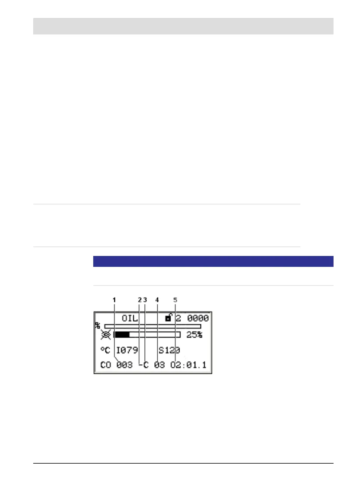
Fig. 8-7 Display for active CO control
1 CO actual value [ppm]
2 – = air is reduced
+ = air is increased
3 C = increasing firing rate
c = falling firing rate
4 Number of optimisation steps
5O
2
actual value – in this case 1.1 vol.%
O
2
 Loading...

