65
4 CMS Components
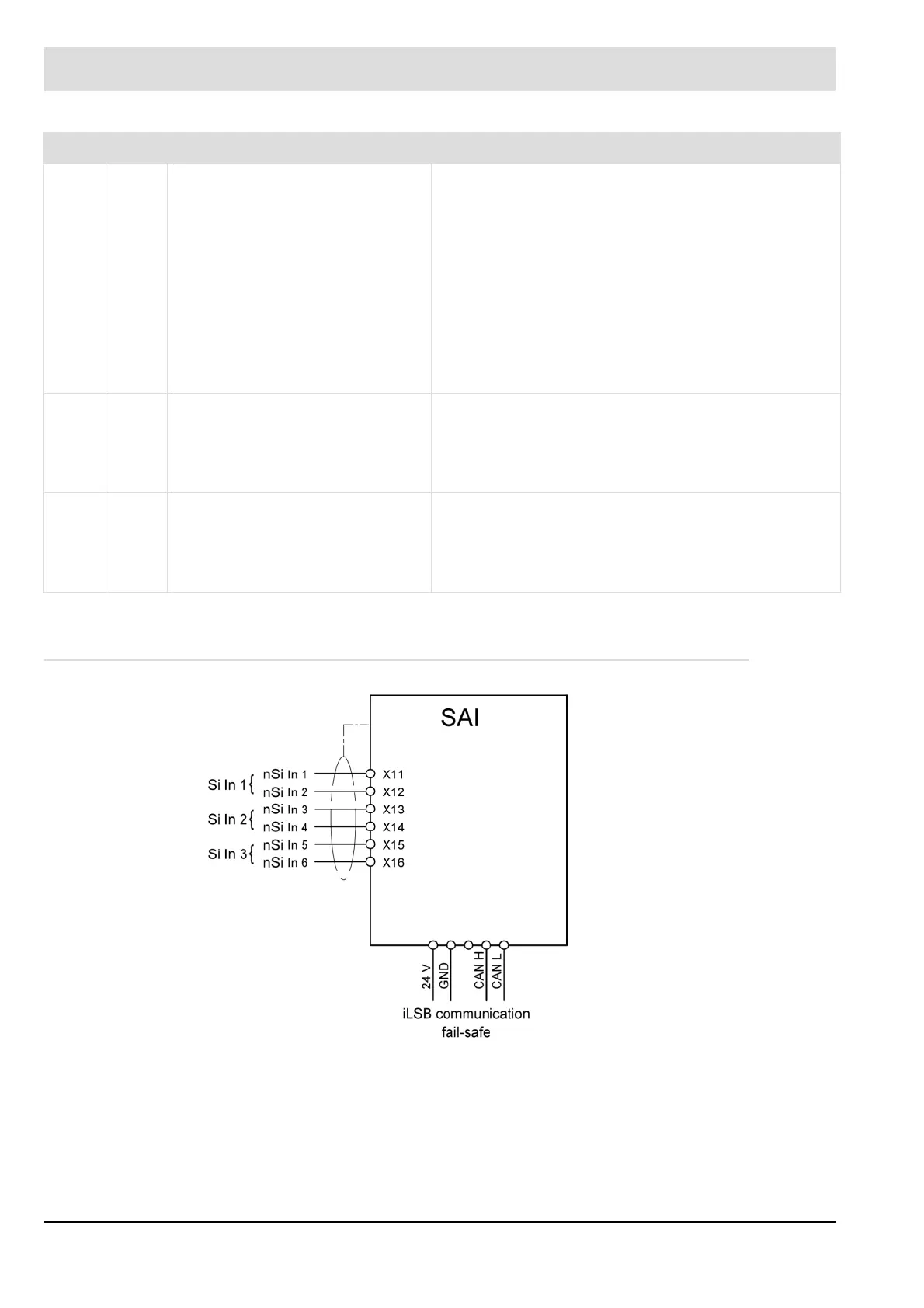
4.6.6 Connection Diagram
Fig. 4-29 SAI connection diagram
iLSB Yel-
low
– Flashing at 2 Hz:
iLSB initialising
– Permanent light:
iLSB successfully initialised
– OFF and ERR-LED OFF:
Passive mode
*
– OFF and ERR-LED ON:
Fault during system layer
initialisation
– Permanent light: iLSB communication OK,
Module is in operation
– Short flashing (60 ms on/140 ms off):
Synchronisation
– Short flashing (140 ms on/60 ms off): IDLE
– Short flashing (50 ms on/50 ms off):
Middleware fault
S1 Yel-
low
– Flashing at 2 Hz:
EEPROM initialising
– Permanent light:
EEPROM successfully
initialised
– OFF: There are no indications/messages from the
middleware.
– ON: There are indications/messages from the
middleware
S2 Yel-
low
– Flashing at 2 Hz:
ICOM initialising
– Permanent light:
ICOM successfully
initialised
– Flashing at 2 Hz:
PEC identification activated.
* Passive mode = PEC not taught-in
Burner firing-rate In operation
Assignment of terminal blocks X11–X16
Si In failsafe input PIN 1 Ref+
nSi In non-failsafe input PIN 2 Input+
PIN 3 Input
PIN 4 GND
 Loading...

