59
4 CMS Components
4.5.4 Functional Description
SDO is a module which is designed for failsafe digital outputs. It enhances the CMS system.
SDO is equipped with 8 failsafe digital outputs These are assigned to the CMS system by soft-
ware functions.
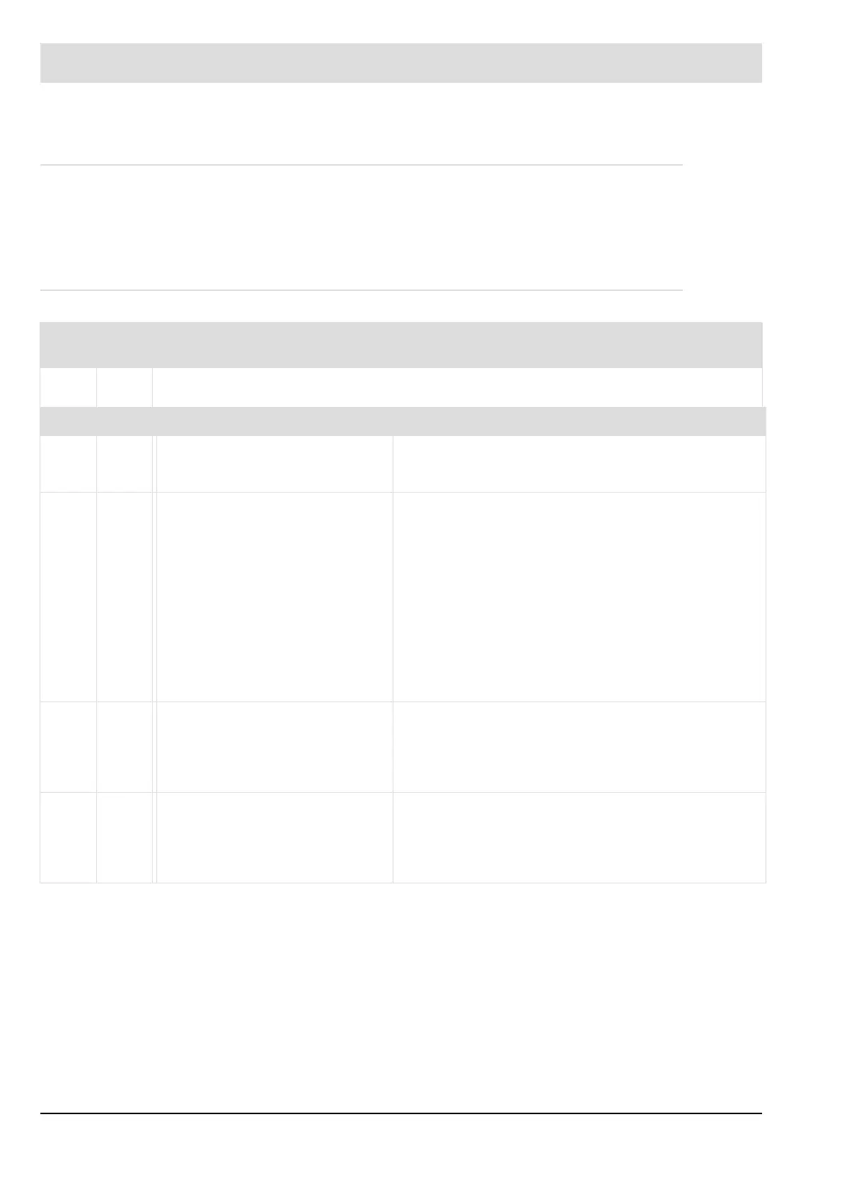
4.5.5 LEDs
LED Col-
our
Explanation
PWR Gree
n
LED is active as soon as the device is supplied with voltage.
Burner firing-rate In operation
ERR – ON: There is a fault
– Flashing at 2 Hz:
Device initialising
– ON: There is a fault.
– OFF: No fault
iLSB Yel-
low
– Flashing at 2 Hz:
iLSB initialising
– Permanent light:
iLSB successfully initialised
– OFF and ERR-LED OFF:
Passive mode
*
– OFF and ERR-LED ON:
Fault during system layer
initialisation
– Permanent light: iLSB communication OK,
Module is in operation
– Short flashing (60 ms on/140 ms off):
Synchronisation
– Short flashing (140 ms on/60 ms off): IDLE
– Short flashing (50 ms on/50 ms off):
Middleware fault
S1 Yel-
low
– Flashing at 2 Hz:
EEPROM initialising
– Permanent light:
EEPROM successfully
initialised
– OFF: There are no indications/messages from the
middleware.
– ON: There are indications/messages from the
middleware
S2 Yel-
low
– Flashing at 2 Hz:
ICOM initialising
– Permanent light:
ICOM successfully
initialised
– Flashing at 2 Hz:
PEC identification activated.
* Passive mode = PEC not taught-in
 Loading...

