213
8 CO/O
2
Control
8.7.2 Display in the Case of Active CO/O2 Control
8.7.2.1 Display with Active CO Control
The CO display replaces the O
2
display as soon as CO control is active.
NOTICE
re Items 2 and 4:
If this display value reaches -32 in case of air reduction (display of Item 2 = – and Item 4 = 32)
and +52 or +54 in case of air increase (display of Item 2 = + and Item 4 = 52 or 54), the CO
control has detected the CO edge and the optimisation point is saved.
8.7.2.2 Display for Active O
2
Trim
8.7.2.3 Status Display in Case of O2 Trim
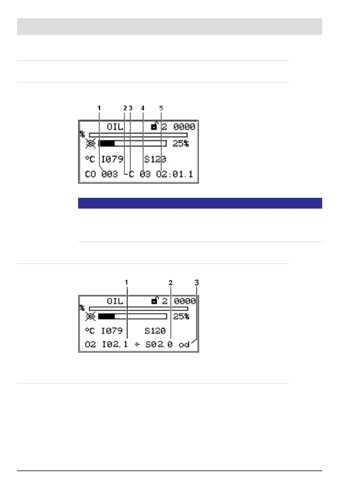
Fig. 8-4 Display for active CO control
1 CO actual value [ppm]
2 – = air is reduced
+ = air is increased
3 C = increasing firing rate
c = falling firing rate
4 Number of optimisation steps
5O
2
actual value – in this case 1.1 vol. %
O
2
Fig. 8-5 Display for active O
2
trim
1O
2
actual value
2O
2
setpoint value
3 Status display
op O
2
trim ready (at burner startup) or O
2
trim switched off temporarily depending on fir-
ing rate (see Chapter Activating O2 Trim
or O
2
trim active (see Chapter 8.7.2.2 Display for Active O
2
Trim).
ot O
2
trim temporarily deactivated (insufficient air, O
2
value under the monitoring bands,
etc.)
od O
2
trim permanently deactivated (malfunction), e.g., test routines at burner startup
not passed, dynamics test negative, O
2
trim temporarily deactivated for longer than
an hour, etc. (see chapter 8.7.2.4 Resetting Faults).
 Loading...

