80
5 Functional Description with Process Diagrams
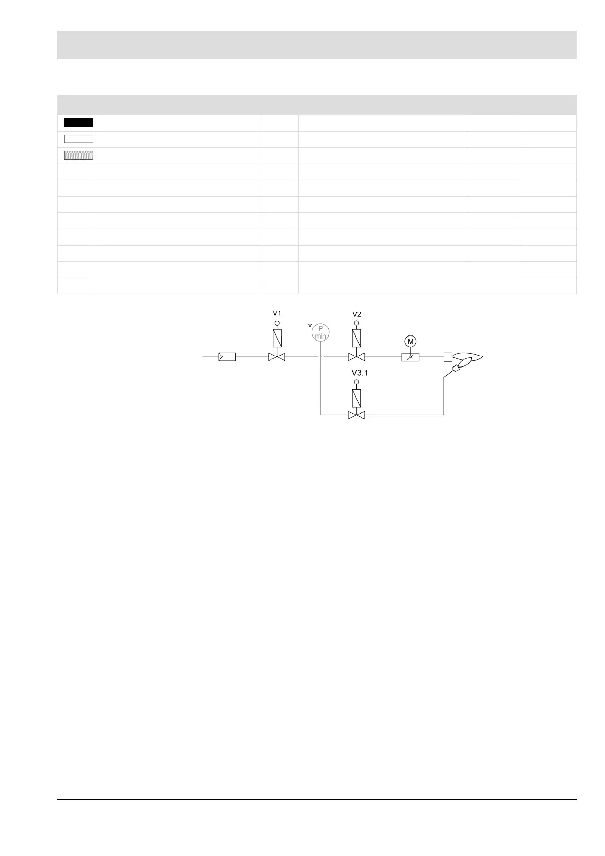
Fig. 5-2 Gas train for standard sequence for gas modulating with pilot burner
Signal bar Significant times and their parameters Standard
Signal must be present. t4* Parasitic light monitoring time P803 5.0 s
Signal must not be present. t5 Pre-ventilation time P318 1 - 999 s
Signal can be present. t6 Transformer pre-activation time P309 3.0 s
t7 1
st
safety time P305 4.0 s
t8 Stabilization time P310 3.0 s
t9 2
nd
safety time P308 3.0 s
t11 Control release delay time P380 0.0 s
t12 Block and bleed of the gas train P334 3.0 s
t13 Post-ventilation time P319 0.0 s
t22 Program monitoring time P304 600 s
t23 Irrelevance time P323 2.0 s
V1 Gas side fuel valve M Gas damper servomotor
V2 Burner side fuel valve P
min
Min. gas pressure monitor
V3.1 Gas side pilot valve V4.1 Burner side pilot valve
 Loading...

