OPERATING PROCEDURES GRT655/655L OPERATOR MANUAL
4-104 Published 3-23-2020, Control # 654-04
Using the Tare Function
The tare function is not shown on the RDM at crane startup.
To show the tare function, do one of the following:
• Press the Screen Toggle Button (1, Figure 4-88) at the
Jog Dial to select the RDM screen control.
From the RCL Setup Screen, press the Tab Button (2).
- or -
• Press the Tab Button (3, Figure 4-88) on the RDM
Navigation Control Pad.
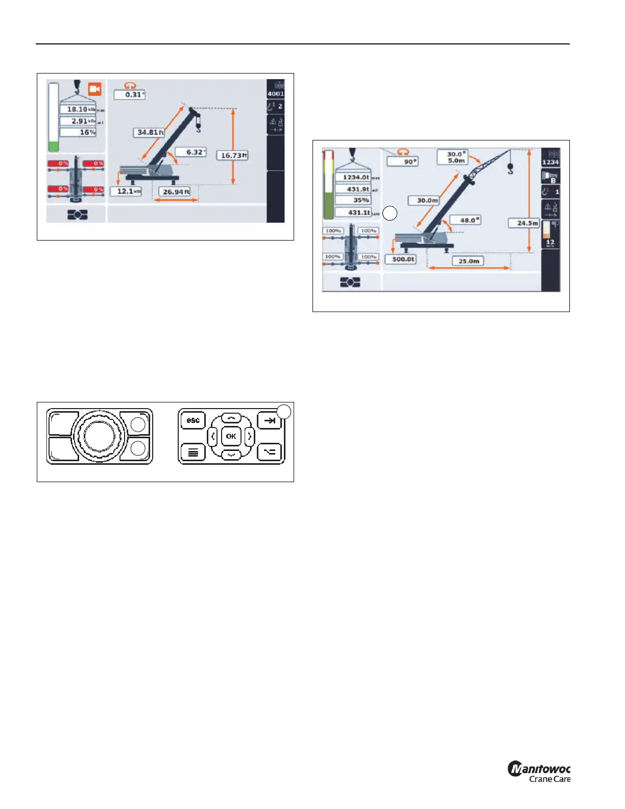
The tare weight (1. Figure 4-89) is shown below the
percentage of the actual versus maximum percent load. The
tare weight value equals the actual weight value until the tare
weight is zeroed out. The operator sets the tare weight to
zero by pressing the Tab Button on either the Jog Dial or the
RDM Navigation Control Pad.
If the Operator changes the Load Chart Code Number, the
tare weight will be reset to equal the current Actual Weight.
To disable the tare function, the operator must switch power
off and back on using the Ignition Key Switch.
NOTE: The tare function does not change nor override the
value of the Actual Load, and does not affect the
RCL and its function lockouts.
Limit Bypass Indicators
In an emergency situation only, the Limit Bypass Switch
located in the cab on the lower right console can be used to
bypass the different limiter systems on the crane. Refer to
the following pages for information regarding the switch’s
operation:
1. Front Limit Bypass Switch (Non-CE Certified Cranes),
page 3-14
2. Limit Bypass Set-Up Switch (CE Certified Cranes),
page 3-15
A Limit Bypass Switch is also located in the cab behind the
operator’s seat on non-CE certified cranes and on the
outside rear of the cab on CE certified cranes:
3. Rear Limit Bypass Switch (Non-CE Certified Cranes),
page 3-19
4. Bridging Switch and Indicator (CE Certified Cranes),
page 3-20
When a Limit Bypass Switch is actuated, the following
indicators on the Rated Capacity Limiter Display Module
(RDM) come on to confirm that the limiters are bypassed (1
through 3, Figure 4-90).

 Loading...


