OPERATING CONTROLS GRT655/655L OPERATOR MANUAL
3-18 Published 3-23-2020, Control # 654-04
Telescope or Auxiliary Hoist Controller
(Single Axis Option)
The Telescope or Auxiliary Hoist (Tele or Aux) Controller (3,
Figure 3-9) is located on the left armrest. The controller
controls the telescope functions when the crane is not
equipped with an auxiliary hoist. Pushing the controller
forward extends the boom and pulling the controller rearward
retracts the boom in.
When equipped with an auxiliary hoist, the controller controls
auxiliary hoist functions and telescope functions are
controlled through a foot pedal. Pushing the controller
forward lowers the hoist rope and pulling the controller
rearward raises the hoist rope.
Swing Controller (Single Axis Option)
The Swing Control Lever (4, Figure 3-9) is located on the
right armrest. Pushing the controller forward rotates the
superstructure clockwise and pulling the controller rearward
rotates the superstructure counterclockwise. The
superstructure can be continuously rotated 360° in the
desired direction.
Hoist Rotation Indicators (Not Shown)
Hoist Rotation Indicators (5, Figure 3-9) for auxiliary and
main hoists are located on top of each single-axis hoist
controller (1, 3, Figure 3-9). Each indicator is electronically
driven by an input signal from a sensor attached to its related
hoist and an output signal from a control module. Each hoist
controller (1, 3) pulses when its hoist is running so the
operator’s thumb can sense it.
FOOT PEDAL CONTROLS
360° Swing Lock Pedal
The 360° Swing Lock Pedal (1, Figure 3-10) is located on the
left side of the cab floor. The pedal activates the swing lock to
prevent superstructure from turning.
360° Swing Lock Release Lever
The 360° Swing Lock Release Lever (2, Figure 3-10) is
located on the left side of the cab floor, directly above the
360° Swing Lock Pedal (1). Lifting up on the lever releases
the 360° swing lock.
Swing Brake Pedal
The Swing Brake Pedal (3, Figure 3-10) is located on the left
side of the cab floor. It actuates the swing brake to slow or
stop swing motion. Braking increases or decreases
proportionately with the amount of foot pressure applied to
the pedal.
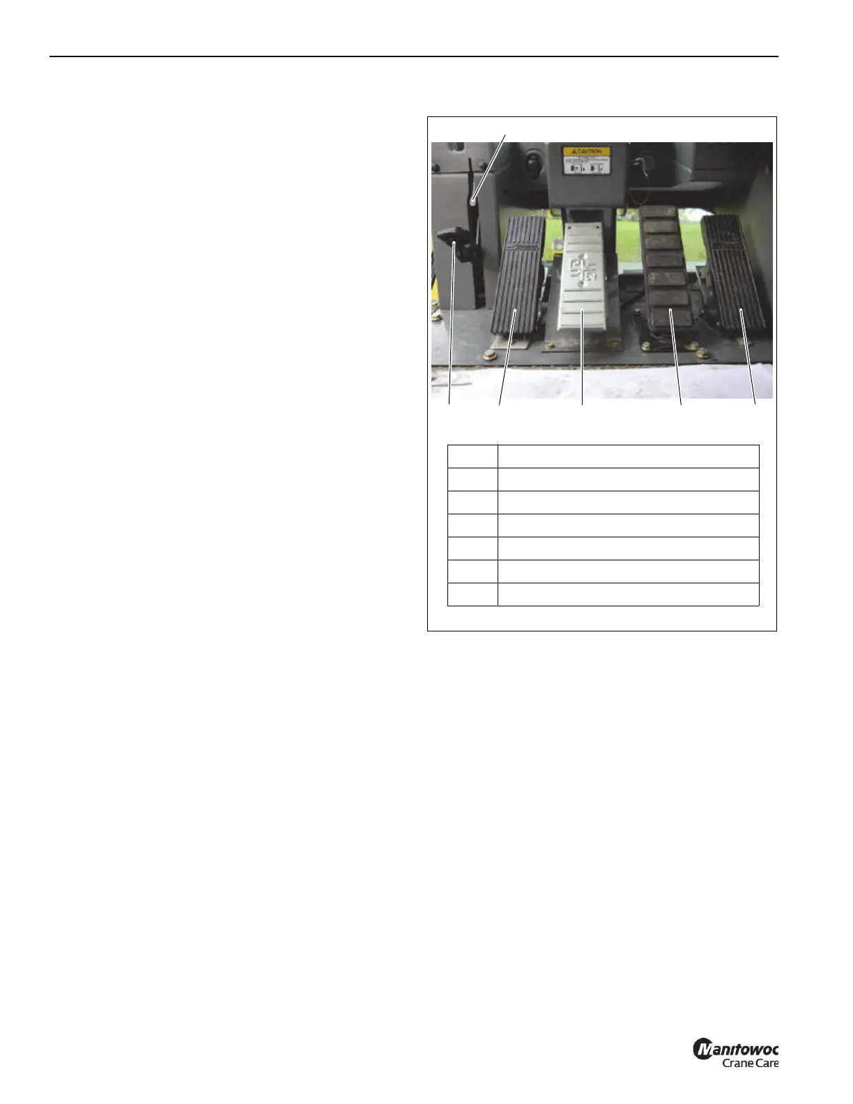
FIGURE 3-10
7649-8A
3
5
2
1
6
4
Item Description
1 360° Swing Lock Pedal
2 360° Swing Lock Release Lever
3 Swing Brake Pedal
4 Telescope Control Foot Pedal
5 Service Brake Pedal
6 Foot Throttle Pedal

 Loading...


