5-32 Published 3-23-2020, Control # 654-04
SET-UP AND INSTALLATION GRT655/655L OPERATOR MANUAL
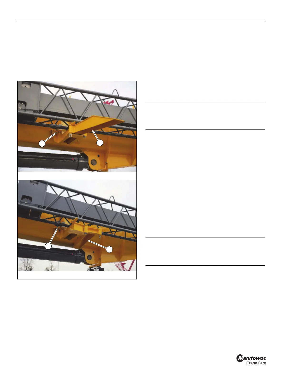
14. Using the tag line, swing the boom extension towards
the boom until the boom extension engages the rear
stowage bracket. Raise the boom as necessary to help
the boom extension engage the rear stowage bracket.
15. Remove the attachment pin (2, Figure 5-34) from its
stowed position and secure the boom extension to the
rear stowage bracket. Secure the attachment pin in
position with retaining clip.
16. Fold in the ramp (1, Figure 5-34) at the rear stowage
bracket.
17. Remove the tag line.
Setting the Offset
Refer to Figure 5-35 through Figure 5-37.
1. Extend and set the outriggers. Swing the boom over the
front of the crane.
2. Remove the hoist rope retaining pins from the boom
extension sheave. Remove the hoist rope from the
sheave, then reinstall the boom extension hoist rope
retaining pin and secure with retaining clip.
3. To set the offset from a lesser degree to higher degree
perform the following procedures.
a. Slowly lower the boom until the boom extension tip
is resting on the ground and pressure is relieved on
the offset link pins.
b. Remove the offset link retaining clips and
attachment pins securing the offset links in the
lesser degree offset position. If going to maximum
offset, stow them in the stowage lugs (3,
Figure 5-37). If going to the intermediate (15
degree) offset, install them in the offset links for that
degree of offset (2,.Figure 5-36).
c. Slowly elevate the boom until the offset links take
the full weight of the boom extension.
d. Reeve the hoist rope as described under normal
erecting procedures.
4. To set the offset from a higher degree to lesser degree,
perform the following procedures.
a. Slowly lower the boom until the boom extension tip
is near ground level.
b. Remove the hoist rope retaining pins from the boom
extension sheave. Remove the hoist rope from the
sheave, then reinstall the boom extension hoist rope
retaining pin and secure with retaining clip.
FIGURE 5-34
1
2
1
2
9216-1
9216-10
CAUTION
To prevent component damage, do not overload the boom
extension anchor fittings or the boom extension base
section when lowering the boom.
CAUTION
To prevent component damage, do not overload the boom
extension anchor fittings or the boom extension base
section when lowering the boom

 Loading...


