Grove Published 3-23-2020, Control # 654-04 4-5
GRT655/655L OPERATOR MANUAL OPERATING PROCEDURES
direction that the block/ball rotates as the fall length
increases. Repeat as necessary until block/ball rotates
no more than 90°.
Using Your Load Chart
NOTE: One of the most important tools of every Grove
crane is the load chart in the crane operator's cab.
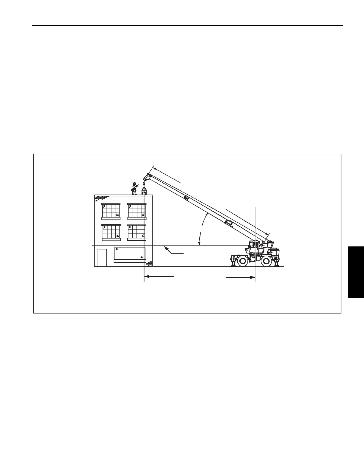
NOTE: Refer to Figure 4-1 for terms to know in
determining lifting capacities.
The load chart contains crane lifting capacities in all
allowable lifting configurations and must be thoroughly
understood by the operator.
The left column is the load radius, which is the distance from
axis of crane rotation to load center of gravity. The top row
lists various boom lengths from fully retracted to fully
extended (with swingaway boom extension). The number at
the intersection of the left column and top row is the total load
limit for that load radius and boom length. The number in
parentheses below the total load limit is required boom angle
(in degrees) for that load.
Another important section is the range diagram. The range
diagram shows operating radius and tip height that can be
achieved at a given boom length and angle. If the operator
knows radius and tip height required for a specific lift, the
angle and boom length can quickly be determined from the
range diagram. Or, if an operator knows boom length and
angle, they can quickly determine tip height and operating
radius.
A lifting diagram is included for over-side, over-rear, and
over-front lifting areas. The lifting area diagram shows
locations of the outrigger jack cylinders in full extended
position are used to mark lifting area boundaries.
Another section contains notes for lifting capacities. Be sure
to read and understand all notes concerning lifting
capacities.
The load chart also gives weight reductions for Grove load
handling devices such as hook blocks, overhaul balls, boom
extension sections, etc., which must be considered as part of
the load. Weight of any other load handling devices such as
chains, slings, or spreader bars must also be added to the
weight of the load.
NOTE: Information in the following paragraph is an
example only of how to compute a lift. Numbers
may not match load chart in the crane cab.
Example: A concrete beam weighing 2268 kg (5000 lb)
needs to be lifted to a height of 9.1 m (30 ft) at a radius of
15.2 m (50 ft) (maximum). The range diagram indicates the
boom must be extended to 18.9 m (62 ft) to reach a height of
9.1 m (30 ft) at a radius of 15.2 m (50 ft).
First check the crane for load handling devices. In our
example, the crane is equipped with a auxiliary boom nose
(rooster sheave) and a five ton overhaul ball. The rooster
sheave is 50 kg (110 lb), and the overhaul ball is 78 kg
(172 lb) for a total of 128 kg (282 lb). The lift requires slings
and spreader bars weighing 159 kg (350 lb) which makes
the total weight for the load handling devices 286 kg (632 lb).
FIGURE 4-1
OPERATING RADIUS
HORIZONTAL
BOOM ANGLE
M
A
I
N
B
O
O
M
L
E
N
G
T
H
AXIS OF ROTATION
4605
TERMS TO KNOW

 Loading...


