OPERATING CONTROLS AND PROCEDURES MLC300 OPERATOR MANUAL
3-68
Published 11-20-19, Control # 234-19
Boom Hoist Operation
The location of the boom control handle varies depending on
the crane’s configuration. Refer to Drum and Control Handle
Identification on page 3-54.
1. If not already done, perform the crane Startup
Procedure on page 3-63
.
2. Select the correct capacity chart and crane configuration
using the RCL/RCI Display. For detailed instructions,
see the RCL/RCI Operation Manual.
3. Boom hoist speed can be adjusted between 25% and
100% to meet operator needs. See the Speed and
Limits Screen topic in the Main Display Operation
Manual for detailed instructions.
4. Make sure the automatic boom stop is set at the proper
angle. For detailed instructions, see the Automatic
Boom Stop Adjustment topic in Section 4 of the MLC300
Service Manual.
5. Turn off the boom hoist park switch. It may be necessary
to raise the boom slightly to disengage the boom hoist
pawl.
6. Increase the engine speed to the desired RPM with the
hand throttle. Press the foot throttle to momentarily
increase the engine speed when more power is
required.
NOTE The VPC setup mode must be ON anytime the boom
is suspended and operated out of the capacity chart.
The VPC Setup Required fault will come and you will
not be able to operate the boom hoist until this step is
taken.
The VPC setup mode must be OFF anytime the
boom is suspended and operated within the capacity
chart. The VPC Setup Prohibited fault will come and
you will not be able to operate the boom hoist until
this step is taken.
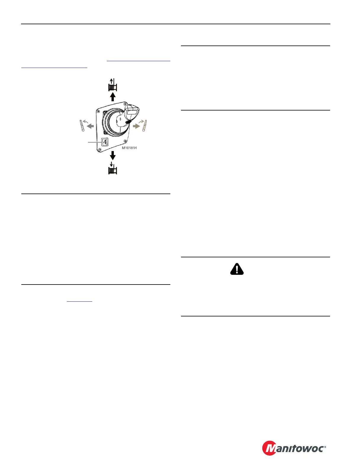
7. Pull the boom control handle BACK from off to RAISE
the boom.
8. Push the boom control handle FORWARD from off to
LOWER the boom.
9. As the boom nears the desired angle, slowly move the
boom control handle toward off to decrease speed.
Then, move the control handle to off to stop the boom
when it reaches the desired angle. The boom hoist
brake will apply to hold the boom in position.
NOTE Besides the boom maximum up limit, a physical
boom stop is provided. The physical boom stop
cushions boom raising between approximately 75°
and the maximum boom angle. The boom stop also
provides a physical stop at 89°.
10. To hold the boom in position for long periods, turn on the
boom park switch. The boom hoist pawl will engage.
CAUTION
Avoid Rigging Damage
Check that the boom hoist wire rope is reeved through all
sheaves and spooled properly onto the drum before
raising the boom from the ground.
• For wire rope and reeving specifications, see the
Boom Assembly Drawing in Section 4 of the MLC300
Operator Manual.
• For instructions on attaching the wire rope to boom
hoist drum, see the Wire Rope Installation topic in
Section 4 of the MLC300 Operator Manual.
Figure 3-18. Boom and Swing Control Handle
Drum 4 – Boom Hoist
CAUTION
Avoid Boom or Luffing Jib Damage
Do not turn on the drum park switch while raising or
lowering the boom. The brake will bring the boom to an
abrupt stop. This action could cause shock load damage
to the boom and the jib. Bring the boom to a smooth stop
with the control handle and then turn on the drum park
switch.
WARNING
Avoid Two-Blocking Hazard
Pay out the load lines while lowering the boom. The load
may contact the boom point sheaves or the jib point
sheaves if this step is not taken. The wire rope or other
parts could break, allowing the load to fall.

 Loading...


