Manitowoc Published 11-20-19, Control # 234-19 4-3
MLC300 OPERATOR MANUAL SETUP AND INSTALLATION
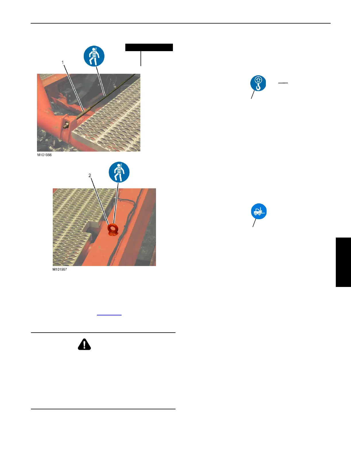
PERSONAL FALL-PROTECTION
Manitowoc has provided lifelines and anchors throughout the
crane and attachment (see Figure 4-1
) to which workers can
attach their personal fall-protection equipment.
HANDLING COMPONENTS
The major components are equipped with lifting lugs. The
lifting lugs are identified by the following symbol in the
assembly and disassembly illustrations.
When lifting lugs are not provided, use nylon lifting slings to
lift the components. If wire rope or chain slings are used,
install protective covering (such as sections of rubber tire)
between slings and component being lifted.
It is the crane owner’s/user’s responsibility to ensure that all
lifting slings, hooks, and shackles are in safe working order
and capable of handling the load applied to them.
In some cases, a forklift is required to lift components. When
required, the lift points are identified by the following symbol
in the assembly and disassembly illustrations.
RETAINING CONNECTING PINS
Connecting pins are retained in various ways:
• Wire-lock pins
• Quick-release pins
• Cotter pins
• Hitch Pins
• Safety pins
• Keeper plates with cap screws and lock washers
Do not operate the crane until all connecting pins are
installed and properly retained.
CRANE WEIGHTS AND SHIPPING DATA
See the Crane Weights topic in Section 1 of this manual for
the weights of individual crane components.
See the MLC300 Product Guide in Section 1 of this manual
for outline and shipping dimensions.
WARNING
Fall Hazard!
To prevent falling from any height during crane assembly
and disassembly, personnel shall wear fall-protection
equipment.
• Anchors and lifelines are designed to handle only one
person at a time.
• Do not use anchors for lifting or pulling loads.
Figure 4-1
Item Description
1 Lifeline
2 Anchor
(4)
Lifting Point
Symbol
Number of
Lifting Points
Figure 4-2
Forklift Symbol
Figure 4-3

 Loading...


