SETUP AND INSTALLATION MLC300 OPERATOR MANUAL
4-142
Published 11-20-19, Control # 234-19
Remove Live Mast Package
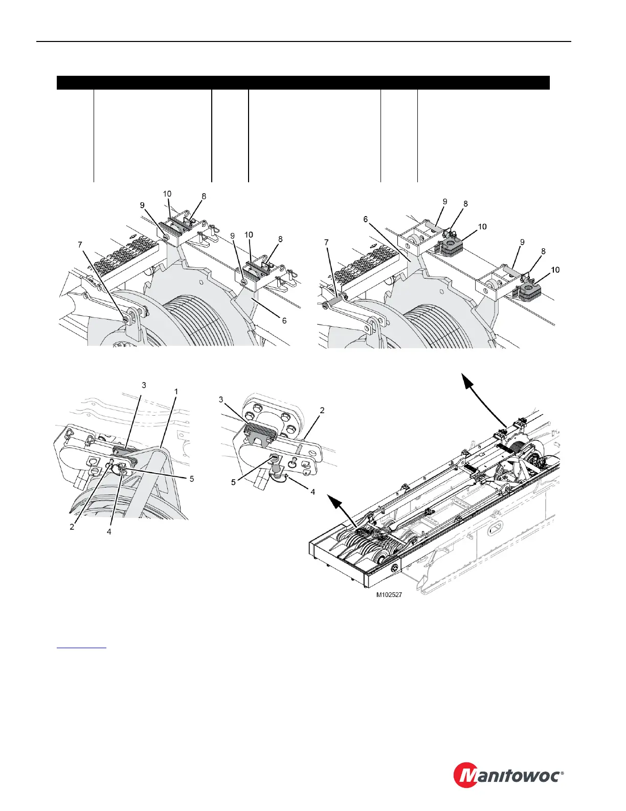
See Figure 4-96 for the following procedure.
1. As they are disconnected, thoroughly clean:
• Hydraulic hose ends and couplers
• Electric cable connectors
• Dust caps
Be sure to install dust caps on all cable connectors
and hydraulic couplers.
2. Disconnect the Drum 2/3 camera cable from the camera
switcher (19, View G) on the rotating bed.
Wire tie the camera cable to the live mast for storage.
3. Disconnect the ground cable (20, View H) from the
ground screw (21) on the rotating bed.
4. Reattach the ground screw and washer to the rotating
bed.
Item Description Item Description Item Description
1 Boom Hoist Equalizer 8 Safety Pin 15 Hydraulic Hose (2)
2 Quick-Release Pin 9 Pin 16 Hydraulic Couplers (2)
3 Shims 10 Shims 17 Electric Cable (WRM1)
4 Safety Pin 11 Hydraulic Hose (5) 18 Receptacle (WRR1-J3)
5 Pin 12 Hydraulic Couplers (5) 19 Camera Switcher
6 Boom Hoist (Drum 4) 13 Electric Cable 20 Ground Cable (from mast)
7 Pin with Safety Pin 14 Receptacle (WRC3) 21 Ground Screw (on rotating bed)
Figure 4-96
View A SHIPPING
View B WORKING
View D
WORKING (2 places)
View C
SHIPPING (2 places)

 Loading...


