Manitowoc Published 11-20-19, Control # 234-19 4-89
MLC300 OPERATOR MANUAL SETUP AND INSTALLATION
Raise Boom Top Wire Rope Guide
See Figure 4-63 for the following procedure.
1. Wrap a small synthetic lifting sling (1, View A) — 340 kg
(750 lb) capacity — around the center sheave in the wire
rope guide (2).
Make sure the lifting sling is on the front side of the wire
rope guide chord (3) and on the rear side of the rope
guard (4).
2. Hoist just enough to loosen the rope guard (4, View A)
and remove the rope guard.
3. Raise the wire rope guide (2, View B) to the working
position.
4. Unpin the struts (5, View A) from the shipping position.
5. Raise the struts (5, View B) to the working position and
pin them to the wire rope guide (2).
6. Disconnect the lifting sling.
7. Reinstall the rope guard (4).
Install Position Light and Wind Speed
Indicator
See Figure 4-63, for the following procedure.
1. Unpin the position light and wind speed indicator
assembly (7, View C) from the storage lugs in the boom
top.
2. Insert the position light and wind speed indicator bracket
(9, View D) into the tube (10) on the right side of the
boom top and install a safety pin (8).
3. Install the other safety pin in the top hole of the bracket
(9, View D).
4. Connect the electric cable (11, View D) from the boom
top to the electric cable from the position light.
5. Connect the electric cable (12, View D) from the boom
top to the electric cable from the wind speed indicator.
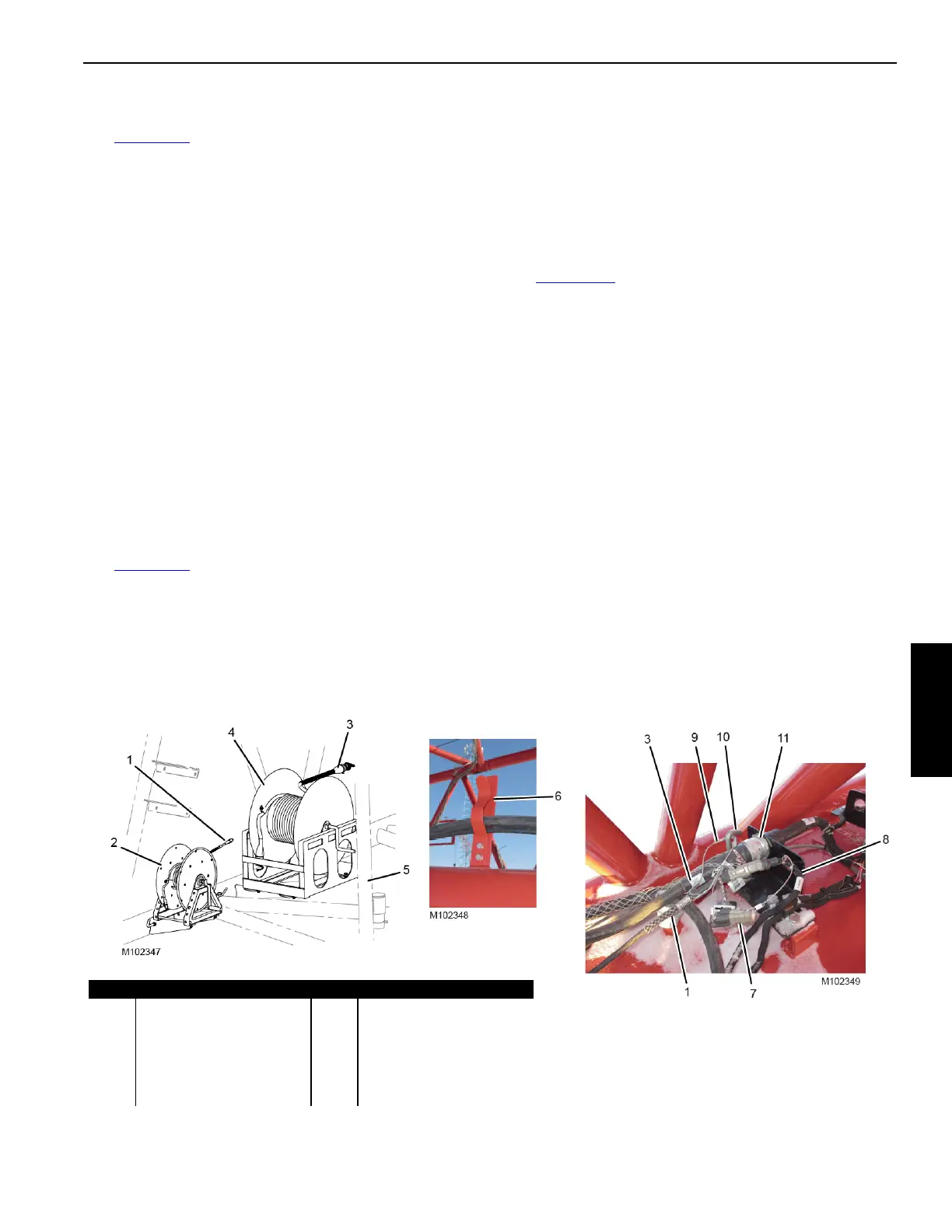
Connect Boom Top Electric Cables
See Figure 4-64 for the following procedure. Refer to the
decal on the side of the boom top for a detailed wiring
diagram.
1. Payout the electric cables (1 and 3, View A) from the
cable reels (2 and 4) in the 12 m (39.4 ft) insert with
sheaves (5).
2. Pull the cables all the way to the boom top (View C).
3. Secure the cables in the cable clips (6, View B) on the
boom sections.
4. Disconnect the CAN terminator (7, View C) from the
CAN NET IN electric cable (8).
5. Connect WN130000 electric cable (1, View C) to the
CAN NET IN electric cable (8)
6. Connect the strain relief (9, View C) to the J-bolt (10).
7. Connect the WBR1 electric cable (3, View C) to the
WBT1 receptacle (11).
Figure 4-64
Item Description Item Description
1 WN130000 Electric Cable 7 CAN Terminator
2 Cable Reel 8 CAN NET IN Electric Cable
3 WBR1 Electric Cable 9 Strain Relief
4 Cable Reel 10 J-Bolt
5 Insert 11 WBT1 Receptacle
6 Cable Clip
View A
View B
View C

 Loading...


