Manitowoc Published 11-20-19, Control # 234-19 4-57
MLC300 OPERATOR MANUAL SETUP AND INSTALLATION
Prepare VPC Trolley
Disregard this procedure if the VPC trolley was shipped on
the rotating bed.
See Figure 4-42
for the following procedure.
1. Position the trailer (1, View A) carrying the VPC trolley
(2) in the assembly area.
2. Remove the tie-downs and blocking securing the VPC
trolley to the trailer.
3. Position the forks from a forklift under the trolley at the
locations shown in View A OR attach lifting slings from
an assist crane to the four lifting lugs (18, View A) on the
trolley frame.
4. Lift the trolley off the trailer and place it on blocking.
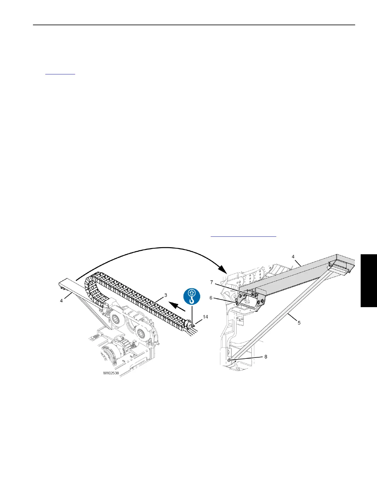
5. Remove the energy chain support (4, View C) from its
shipping position on the VPC trolley.
6. Install the energy chain support (4, View E) in the
working position on the VPC trolley.
7. Disconnect the hydraulic hoses (9, View D) from the
couplers on the storage bracket (10).
8. Remove the pins (11, View B) from the energy chain
supports (12 and 13).
9. Attach a sling from the fork of the forklift or from an assist
crane to the lifting link (14, View B) on the energy chain
(3).
10. Lift the energy chain out of the energy chain supports
(12 and 13, View B) and roll the energy chain (3) forward
onto the energy chain support (4, View H).
11. While holding the energy chain with the lifting sling:
a. Remove the energy chain supports (12 and 13,
View B) from the shipping positions.
b. Reinstall pins (11, View B) in the holes in the energy
chain supports (12 and 13).
c. Store the energy chain supports (12 and 13) in the
job box.
12. Lower the energy chain and disconnect the lifting sling.
13. Hold the hose storage bracket (10, View G) so it cannot
fall and remove the safety pins (16) and the pivot pin
(17) securing the bracket to the VPC trolley.
14. Remove the hose storage bracket from the VPC trolley.
15. Connect the dust caps to the couplers on the hose
storage bracket.
16. Install the hose storage bracket on the right side of the
rotating bed AFTER the VPC trolley is installed. See
Figure 4-45 on page 4-62
.
Figure 4-42 continued
View E
WORKING
View H
WORKING