Manitowoc Published 11-20-19, Control # 234-19 4-141
MLC300 OPERATOR MANUAL SETUP AND INSTALLATION
Legend for Figure 4-94
Remove Drum 2
See Figure 4-94 for the following procedure.
An assist crane capable of lifting 4 650 kg (10,253 lb) to a
height of approximately 6 m (20 ft) above the ground is
required for the procedure.
1. As they are disconnected, thoroughly clean:
• Hydraulic hose ends and couplers
• Electric cable connectors
• Dust caps
2. Disconnect the electric cable (12, View B) from the drum
(1) at the electric receptacle (13) on the rotating bed.
a. Connect a dust cap to the cable end and to the
receptacle.
b. Wire tie the electric cable to the drum for storage.
3. Disconnect four hydraulic hoses (10, View D) at the
hydraulic couplers (11) on the drum (1).
a. Disconnect the dust caps from the storage couplers
(16, Figure 4-95
) on the rotating bed and connect
the dust caps to the couplers on the drum.
b. Connect the hydraulic hoses from the rotating bed
to the storage couplers (16, Figure 4-95
).
4. Attach the Manitowoc supplied lifting slings (2, View A)
to the hook of the assist crane.
5. Connect the other end of the lifting slings (2, View A) to
the lifting lugs (3) on the drum (1) with the Manitowoc
supplied shackles (4).
6. Remove the hitch pins (8, View E) and the pins (9) from
the working position and store the pins (9, View F) and
the hitch pins (8).
7. Remove pins (7, View C) from the working position and
store the pins (7, View F).
8. Slowly and carefully lift the drum (1) out of the rotating
bed and place it on trailer.
9. Disconnect the shackles (4, View A) and the lifting slings
(2) from the drum.
10. Secure the drum to the trailer with tie-downs.
Remove Drum 3
Drum 3 removal is identical to Drum 2 removal with the
following exceptions:
• The top connecting holes in Drum 3 are pinned to the top
connecting holes in the rear of Drum 2.
• The electric cable (14) from Drum 3 is connected to the
electric receptacle (15) on the rotating bed.
Install/Store Rotating Bed Platforms
The rotating bed platforms (1 and 2) can be stored as shown
in Figure 4-29 on page 4-38
.
Item Description
1Drum 2
2 Lifting Sling (4): 2,8m (9 ft) long
3 Lifting Lug (4)
4 Shackle (4): 25 t (28 USt)
5 Rotating Bed Lugs
6 Rotating Bed Lugs
7 Pin with Cotter Pins (2)
8 Hitch Pin with Hair-Pin Cotter (2)
9Pin (2)
10 Hydraulic Hose (4)
11 Hydraulic Coupler (4)
12 Electric Cable (WRF1-P1)
13 Electric Receptacle (WRR1-J4)
14 Electric Cable (WRF1-P1)
15 Electric Receptacle (WRR1-J5)
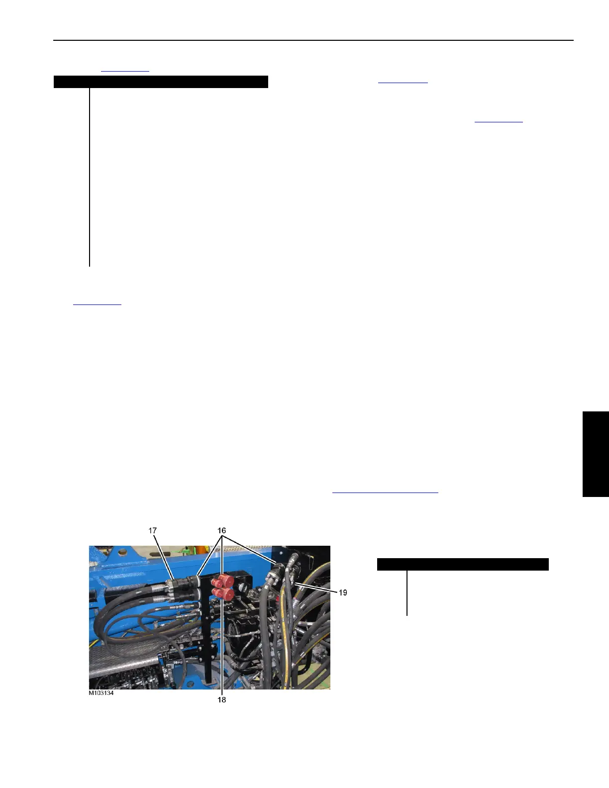
Item Description
16 Storage Couplers with Dust Caps
17 Drum 3 Hydraulic Hoses
18 Store Drum 2 Hydraulic Hoses Here
19 Drum 4 Hydraulic Hoses
Figure 4-95
View of Right
Inboard Side of
Rotating Bed

 Loading...


