Manitowoc Published 11-20-19, Control # 234-19 4-157
MLC300 OPERATOR MANUAL SETUP AND INSTALLATION
Store Right Side Rear View Mirror
This mirror is optional.
Reverse the installation steps to store the mirror (see Deploy
Right Side Rear View Mirror on page 4-19).
Store RCL Light
Reverse the installation steps to store the RCL light (see
Raise RCL Light to Working Position on page 4-19
).
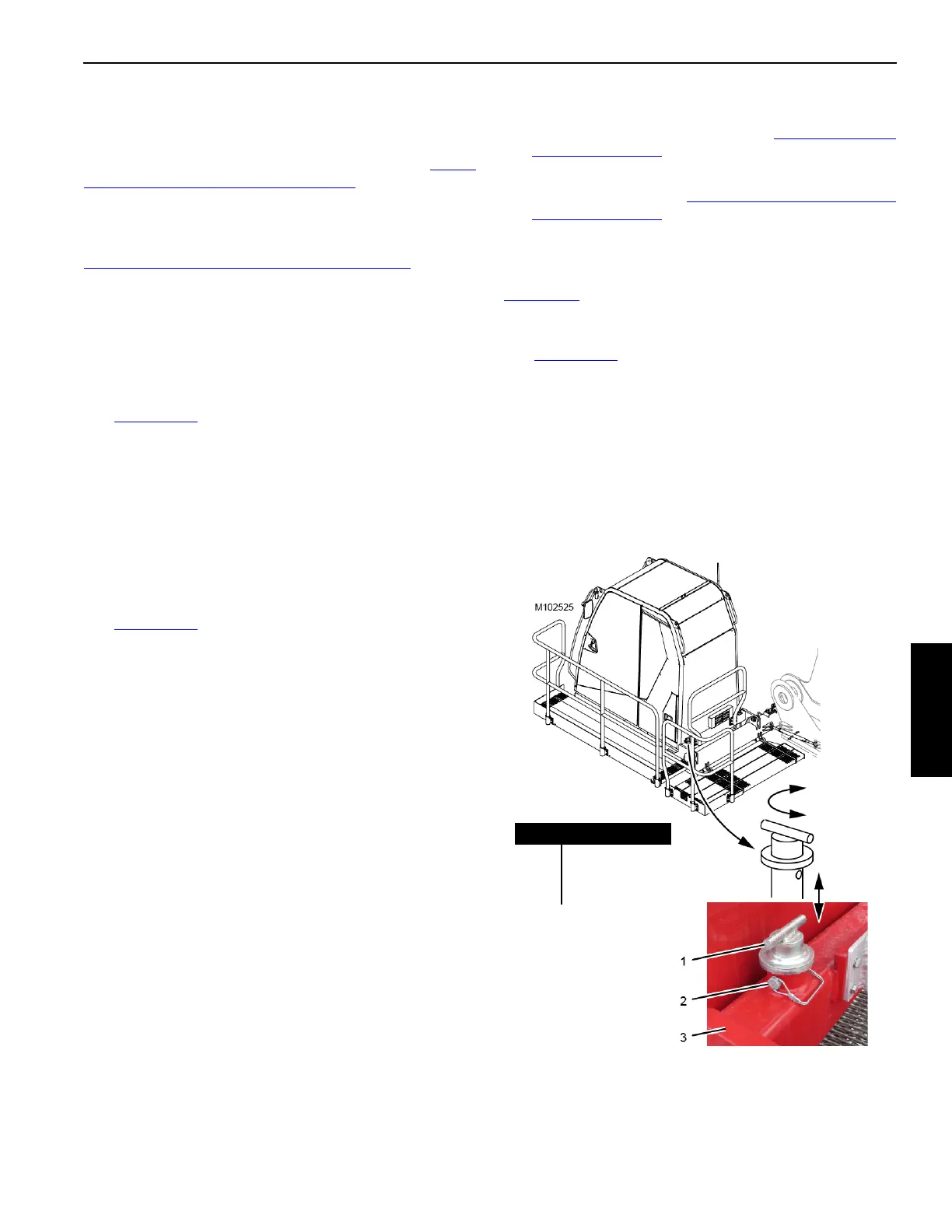
Move Cab Tilt Stop Pins to Shipping Position
This step must be performed to allow the cab to be rotated
down for shipping.
This step must be performed before you store the cab rear
platform.
See Figure 4-104
for the following procedure.
1. Using the remote control, tilt the cab up a few degrees
above horizontal.
2. Remove the safety pins (2).
3. Pull the stop pins (1) up and rotate them to align the
connecting holes in the shipping position.
4. Install the safety pins (2).
Store Cab Rear Platform
See Figure 4-103 for the following procedure.
1. Remove the safety pins (12, View E).
2. Remove the handrail (11) from the cab rear platform (9).
3. Attach the handrail to a shipping pallet and secure the
pallet to a trailer.
4. Reinstall the safety pins (12, View E) on the cab rear
platform.
5. Support the cab rear platform (9, View D) so it cannot
fall. It weighs 30 kg (66 lb).
6. Remove the quick-release pins (10, View D) from the
operating position and raise the platform to the shipping
position (View C).
7. Install the quick-release pins (10, View C) to secure the
platform in the shipping position.
Secure Operator Cab
1. Stop the engine in the cab.
2. Park all crane functions in the cab.
3. Turn off all accessories in the cab.
4. Remove all keys from the control console in the cab.
5. Close and latch all cab windows.
6. Close and lock the cab door.
7. Reactivate the remote control. See Activating Remote
Control on page 4-9.
8. Restart the crane engine with the start switch on the
remote control. See Starting Engine with Remote
Control on page 4-9.
Install Window Covers
If equipped, install the operator cab window covers. See
Figure 4-15
.
Store Operator Cab
See Figure 4-103 for the following procedure.
1. Remove the pin (4, View B)
2. Remove the hitch pin (2, View B).
3. Rotate the operator cab to the shipping position (View
A).
4. Install the hitch pin (2, View A).
5. Connect the turnbuckle (5, View A) to the shipping lugs
(6) on the rotating bed (7) with the pin (4).
Figure 4-104
WORKING Position
(2 places)
Item Description
1 Stop Pin (2)
2 Safety Pin (2)
3 Cab Support
SHIPPING
Position

 Loading...


