SETUP AND INSTALLATION MLC300 OPERATOR MANUAL
4-74
Published 11-20-19, Control # 234-19
BOOM AND JIB RIGGING — GENERAL
Assist Crane Requirements
The MLC300 can be used to handle, assemble, and
disassemble the boom and jib components. See the Crane
Weights topic in Section 1 the MLC300 Operator Manual for
the weights of boom and jib components.
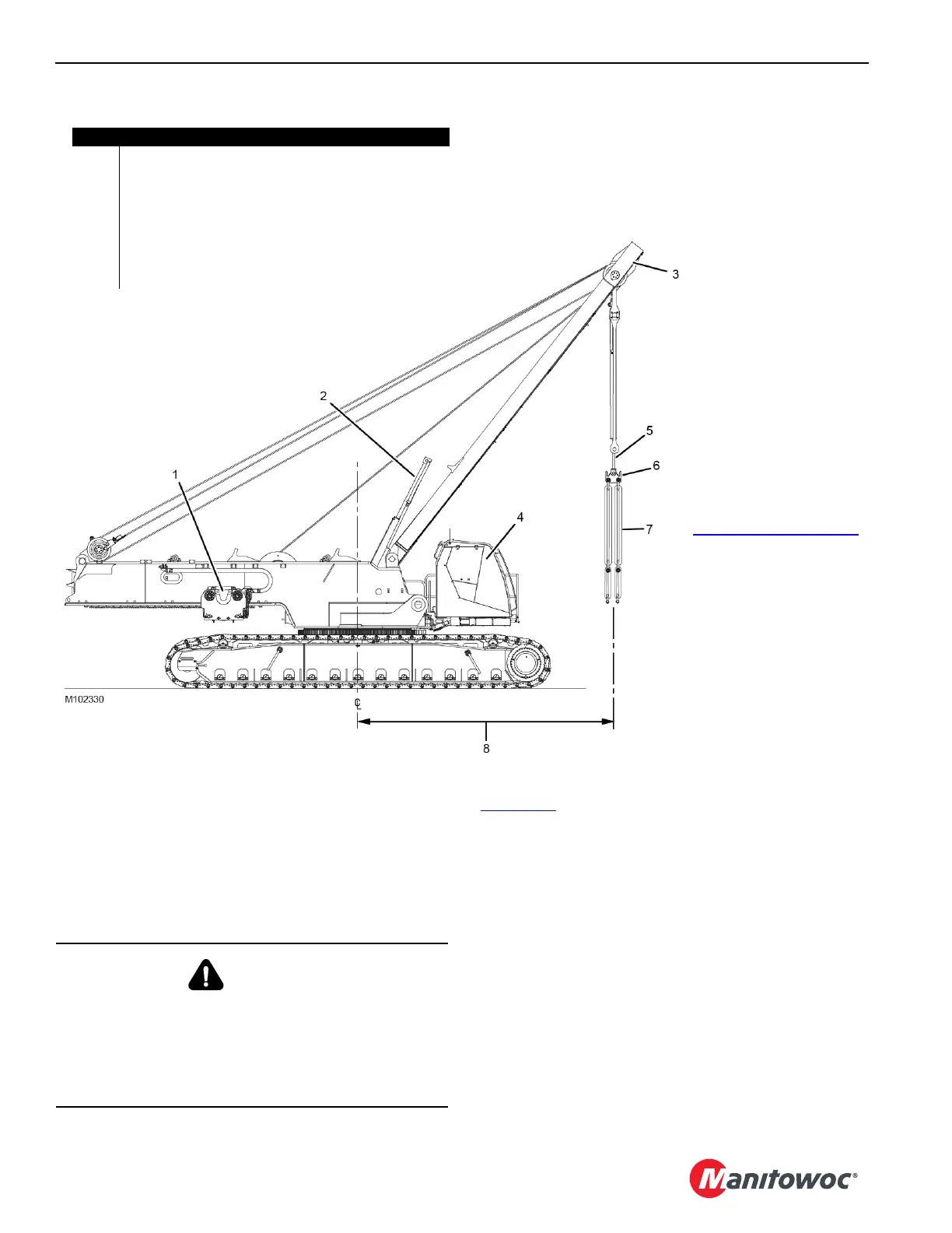
The MLC300 must be in the following configuration
(Figure 4-54
):
• Counterweight tray and counterweight boxes NOT
INSTALLED.
• Mast assist arms (2) fully raised.
• Lifting link (6) attached to the self-erect cylinder (5).
• Appropriate lifting slings and shackles (7) attached the
lifting link (6).
• Liftcrane Mast Capacities chart selected in the
configuration screen of RCL/RCI Display.
• Mast (3) operated between the fully extended mast
assist arms and the maximum allowable radius (8).
• Radius (8) and capacity limited to that given in the
Liftcrane Mast Capacities chart at the end of this section.
Figure 4-54
Item Description
1 VPC Trolley Installed or Removed
2 Mast Assist Arms (fully raised)
3 Live Mast in Operating Range
4 MLC300 Assembled WITHOUT COUNTERWEIGHT
5 Self-Erect Cylinder
6 Lifting link
7 Lifting Slings and Shackles
8 See Liftcrane Mast Capacities Chart
– See Figure 4-32 on page 4-44
DANGER
Falling Load Hazard!
Prevent structural failure of components:
• Do not exceed the lifting capacities given in the
Liftcrane Mast Capacities chart at the end of this
section.

 Loading...


