Manitowoc Published 11-20-19, Control # 234-19 4-21
MLC300 OPERATOR MANUAL SETUP AND INSTALLATION
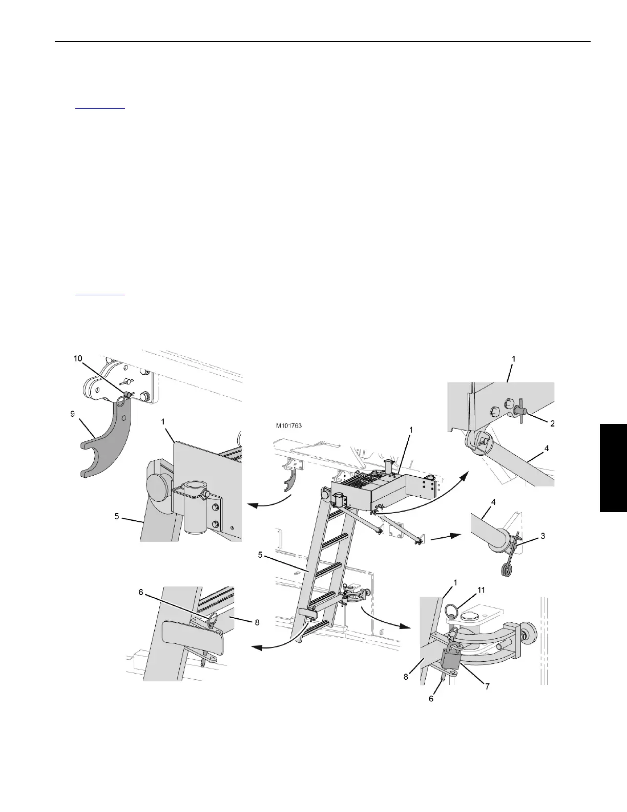
Move Rotating Bed Left-Front Platform to
Working Position
See Figure 4-18 for the following procedure.
1. Remove the quick-release pins (2, View AS) and pins (3,
View BS) to unpin the left-front platform (1, View CS)
from the shipping position.
2. Rotate the left-front platform (1, View CW) up to the
working position.
3. Pin the platform braces (4, View BW) to the lugs on the
rotating bed with the pins (3).
4. Store the quick-release pins (2, View AW) in the holes in
the left-front platform (1).
Move Rotating Bed Left-Front Ladder to
Working Position
See Figure 4-18 for the following procedure.
1. Remove the quick-release pins (6, View DS and ES) and
the padlock (7, View ES) to disconnect the left-front
ladder (5, View DS) from the ladder support arm (8).
2. Unhook the left-front ladder (5, View FS) from the
storage brackets (9).
3. Place the ladder to the side temporarily.
4. Remove the pins (10, View FS), lower the storage
brackets (9, View FW) to the working position and install
the pins (10).
5. Remove the quick-release pin (11, View DS), swing the
support arm (8, View DW) out, and reinstall quick-
release pin (11, View DW).
6. Hook the left-front ladder (5, View FW) onto the left-front
platform (1) and rest the ladder against the support arm
(9, View DW and EW).
7. Install the quick-release pins (6, View DW and EW) to
connect the left-front ladder (5) to the support arm (8).
8. Store the padlock (7, View DW).
Figure 4-18 continued
View AW
View BW
View CW
View DW
View EW
View FW

 Loading...


