Manitowoc Published 04-06-18, Control # 231-14 4-47
MLC650 VPC-MAX™ OPERATOR MANUAL SET-UP AND INSTALLATION
See Figure 4-42 for the following procedure.
NOTE: Series 1, 2, or 3 counterweight can be installed at
this time.
A minimum of Series 1 counterweight is required to
install the partial boom with the fixed mast.
1. If not already done, drive the counterweight tray to the
minimum working position of 4.00 m as indicted in the
VPC-MAX calibration screen (View C, Figure 4-38 on
page 4-40).
2. Remove the counterweight chain assemblies (2) from
the stored position in the counterweight tray.
3. Attach the two SL 4 slings (3) to the assist crane and
around the lugs on one counterweight box.
4. Boom, swing, and hoist as necessary to position the box
on the desired side of the counterweight tray.
5. Lower the box so the counterweight box alignment
lugs (4) engage the counterweight tray alignment
lugs (5).
Each additional box must have the alignment lugs
engage with the alignment lugs on the box below.
6. Remove the slings.
7. Attach the slings around the lifting lugs on two
counterweight boxes.
8. Boom, swing, and hoist as necessary to position the
boxes on the opposite side of the counterweight tray.
9. Lower the boxes so the lower counterweight box
alignment lugs engage the counterweight tray alignment
lugs.
Lower each additional box so the alignment lugs engage
with the alignment lugs on the box below.
10. Remove the slings.
11. Continue to install two boxes, alternating from side to
side.
12. Install one box to level the sides.
13. Install the counterweight chain assemblies (2) by
threading the chain through each counterweight lifting
lug and around the counterweight tray lug (6). The
counterweight chain assemblies are designed to
minimize counterweight movement during travel and
operation permitted by Manitowoc’s operating
instructions.
14. Connect the counterweight chain assemblies to the
turnbuckle (7) hooks.
15. Tighten the turnbuckles until the counterweight chain
assemblies around the lugs are snug.
NOTE: The ratchet on the turnbuckle must be flipped in
one direction to tighten the turnbuckle and in the
opposite direction to loosen the turnbuckle.
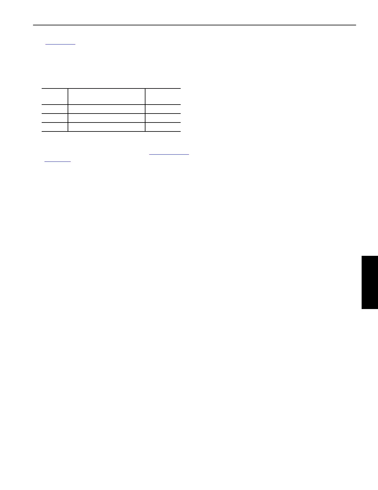
Series Total Counterweight
Boxes
each Side
1 200 000 kg (440,900 lb) 9
2 300 000 kg (661,300 lb) 14
3 400 000 kg (881,800 lb) 19

 Loading...


