Manitowoc Published 04-06-18, Control # 231-14 1-1
MLC650 VPC-MAX™ OPERATOR MANUAL INTRODUCTION
SECTION 1
INTRODUCTION
CRANE DATA
See the end of this section for crane data specific to your
crane:
• Basic Specifications
• EC Declaration (if applicable)
CRANE/ATTACHMENT IDENTIFICATION
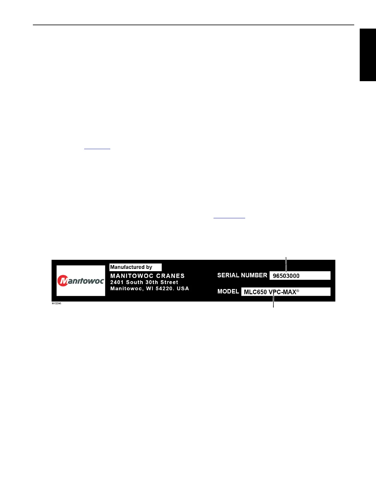
An identification label is attached to the outside of the
operator’s cab (see Figure 1-1
) and to the attachments (such
as luffing jib and VPC-MAX) available for this crane.
The crane or attachment model, application, and serial
number are provided on the label.
For the exact location of the identification labels on your
crane and attachments, see the Nameplates and Decals
Drawing in Section 2 of this manual.
CRANE ORIENTATION
The terms RIGHT, LEFT, FRONT, REAR used in this manual
see operator’s right, left, front, and rear sides when seated in
the operator’s cab looking forward.
• The boom is on the front of the upperworks.
• The crawler drive shafts are at the rear of the crawlers
and carbody.
OUTLINE DIMENSIONS
See Outline Dimension Drawing at the end of this section.
WEIGHTS OF COMPONENTS
See Crane Weights publication at the end of this section.
IDENTIFICATION OF VPC-MAX
COMPONENTS
See Figure 1-2 for identification of the VPC-MAX
components. See Section 1 in the MLC650 Crane Operator
Manual for identification of the crane components.
FIGURE 1-1
Serial
Number
Model
Number

 Loading...


