SET-UP AND INSTALLATION MLC650 VPC-MAX™ OPERATOR MANUAL
4-106
Published 04-06-18, Control # 231-14
Removing the Partial Boom Assembly
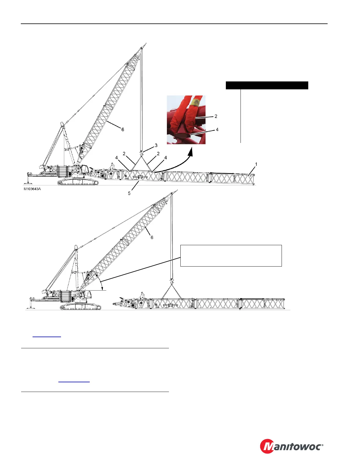
See Figure 4-87 for the following procedure.
1. Attach four SL 6 slings (2, View A) to the shackles on the
equalizer (3, View A) and to the lifting lugs (4, View A)
on the 12M insert (5, View A).
2. Remove the partial boom from the crane using the fixed
mast (6, View B). See Section 4 of the Crane Operator
Manual for boom butt to crane unpinning instructions.
3. Set the partial boom on blocking at ground level.
4. Detach the slings from the equalizer and from the insert.
5. Disassemble the partial boom and prepare it for storage
or shipping:
• See Section 4 of the Crane Operator Manual for
boom disassembly instructions.
• Either an assist crane or the fixed mast can be used
to disassemble the partial boom.
FIGURE 4-87
View B
View A
Item Description
1 Equalizer Insert
2 SL 6 Sling – 5 m (16.40 ft),
31 751 kg (70,000 lb) (qty 4)
3 Equalizer
4 Lifting Lug (qty 4)
512M Insert
6Fixed Mast
Operating Range:
- 39.7-64.5° for Standard Boom (#680)
- 46.8-64.5° for Wide Boom (#685-680)
CAUTION
Mast Damage!
Do not lower the fixed mast below the minimum angle
specified in Figure 4-87 during the following steps.
Structural damage could result.

 Loading...


