Manitowoc Published 04-06-18, Control # 231-14 4-117
MLC650 VPC-MAX™ OPERATOR MANUAL SET-UP AND INSTALLATION
Removing the Fixed Mast Inserts
See Figure 4-97 for the following procedure.
NOTE: It is acceptable to cantilever both inserts from the
mast butt.
1. Attach four SL 4 slings (1) to the lifting lugs (2) on the
second fixed mast insert (3).
2. Attach the slings to the assist crane.
3. Remove the safety pins (4) from the retaining
pins (5, View B) and slide the retaining pins out.
4. Using the assist crane, lift the insert up and away from
the end of the first fixed mast insert (6) so the fixed
pins (7, View A) on the second insert disengage the
hooked connectors on the first insert.
5. Slide the retaining pins in.
6. Install the safety pins.
7. Disconnect the slings from the second insert.
8. Attach the slings to the lifting lugs on the first insert.
9. Remove the first insert from the fixed mast butt by
repeating step 3
through step 7.
10. Disconnect the slings from the first insert.
11. Prepare the inserts for storage or shipping as necessary.
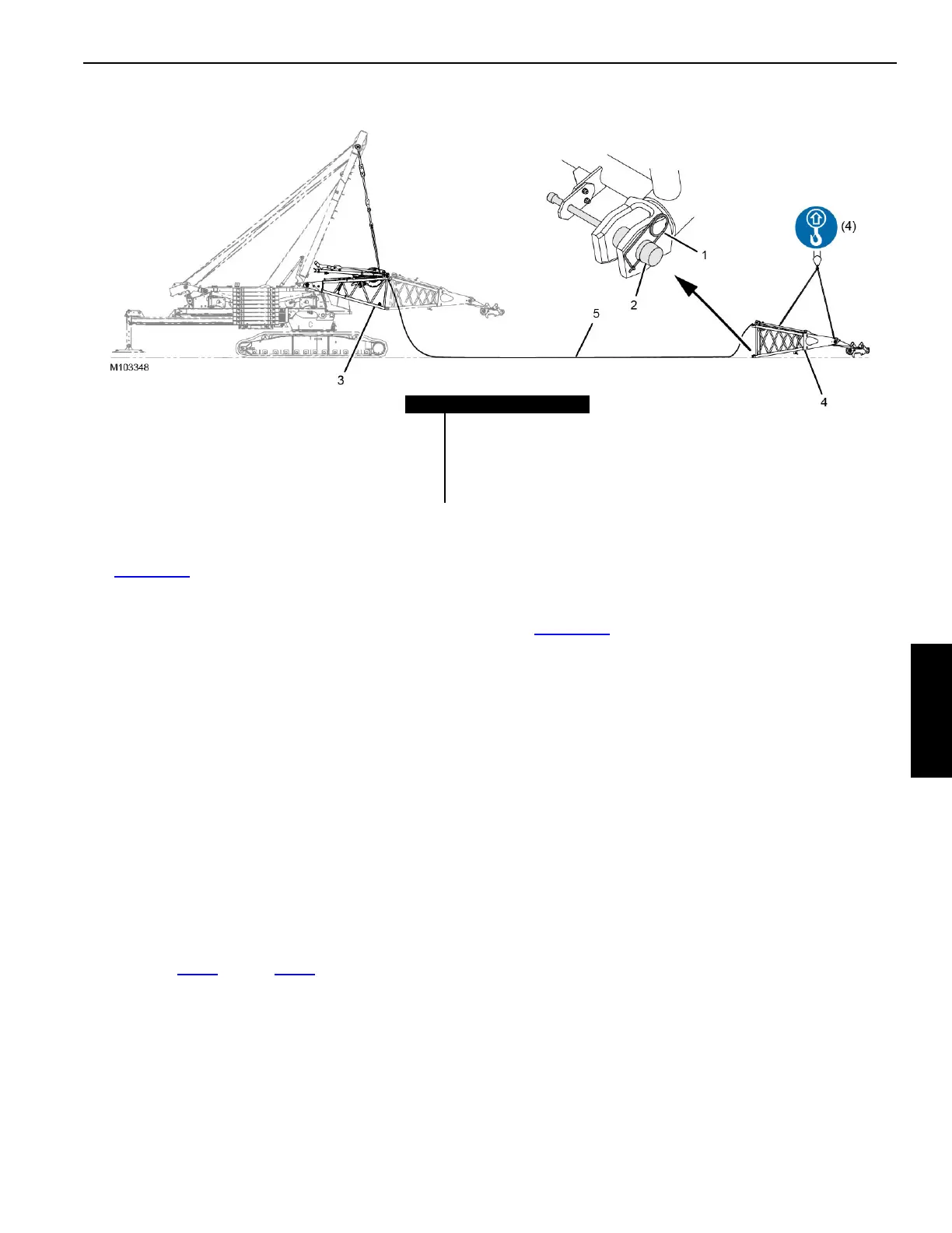
Attaching the Fixed Mast Top to the Butt
See Figure 4-98 for the following procedure.
1. Attach the four SL 6 slings already on the fixed mast
top (4) to the assist crane.
2. Remove the safety pins (1) from the lower retaining
pins (2).
3. Slide the retaining pins out.
4. Spool the boom hoist wire rope (5) onto the boom hoist
drum in the mast butt while performing the next step.
5. Using the assist crane, lift the mast top into position at
the end of the fixed mast butt (3) so the fixed pins on the
mast top engage the hooked connectors on the mast
butt.
6. Lower the mast top until the bottom connection holes
align.
7. Slide the retaining pins back in.
8. Install the safety pins.
FIGURE 4-98
Item Description
1 Safety Pin (qty 2)
2 Retaining Pin (qty 2)
3 Fixed Mast Butt
4 Fixed Mast Top
5Boom Hoist Wire Rope

 Loading...


