SET-UP AND INSTALLATION MLC650 VPC-MAX™ OPERATOR MANUAL
4-30
Published 04-06-18, Control # 231-14
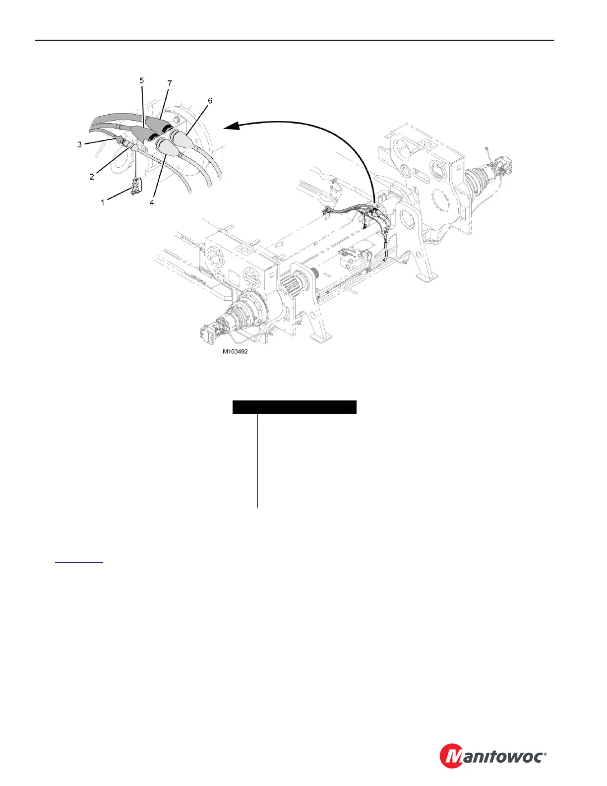
Connecting the Electrical Cables
See Figure 4-29 for the following procedure.
1. Remove the dust caps from the plugs.
2. Remove the terminating resistor (1) from CAN plug
WVH1-J2 (2) on the actuator and mate the resistor to
the provided dust cap.
3. Connect CAN plug WVH1-J2 to CAN plug WVB5-P1 (3)
on the VPC-MAX beam.
4. Connect electrical plug WVH1-J4 (4) on the actuator to
electrical plug WVB4-P1 (5) on the beam.
5. Connect electrical plug WVH1-J1 (6) on the actuator to
electrical plug WVB3-P1 (7) on the beam.
FIGURE 4-29
Item Description
1 Terminating Resistor
2CAN Plug WVH1-J2
3 CAN Plug WVB5-P1
4 Electrical Plug WVH1-J4
5 Electrical Plug WVB4-P1
6 Electrical Plug WVH1-J1
7 Electrical Plug WVB3-P1

 Loading...


