SET-UP AND INSTALLATION MLC650 VPC-MAX™ OPERATOR MANUAL
4-124
Published 04-06-18, Control # 231-14
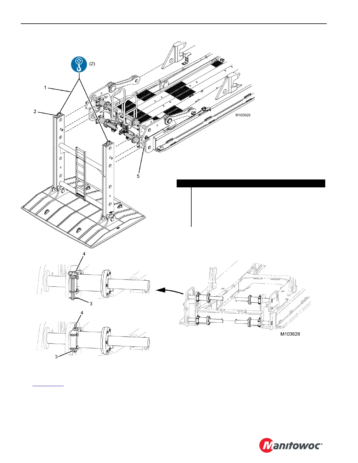
Removing the Auxiliary Member
See Figure 4-104 for the following procedure.
1. Using an assist crane, attach two SL 4 slings (1) to the
auxiliary frame lift points (2).
2. Remove the hair pin cotters (3) from the hitch pins (4).
3. Remove the hitch pins from the working position and
install them in the stored position.
4. Install the hair pin cotters.
5. Retract the powered retaining pins (5).
6. Using the assist crane, remove the auxiliary frame
assembly from the VPC-MAX beam.
FIGURE 4-104
Item Description
1 SL 4 Sling – 3,80 m (12.50 ft), 11 340 kg (25,000 lb) (qty 2)
2 Auxiliary Frame Lift Point (qty 2)
3 Hair Pin Cotter (qty 4)
4 Hitch Pin (qty 4)
5 Powered Retaining Pin (qty 4)
STORED POSITION
WORKING POSITION

 Loading...


