Manitowoc Published 04-06-18, Control # 231-14 6-13
MLC650 VPC-MAX™ OPERATOR MANUAL MAINTENANCE
VPC-MAX LIMIT SWITCHES
Adjusting the Beam Limit Switches
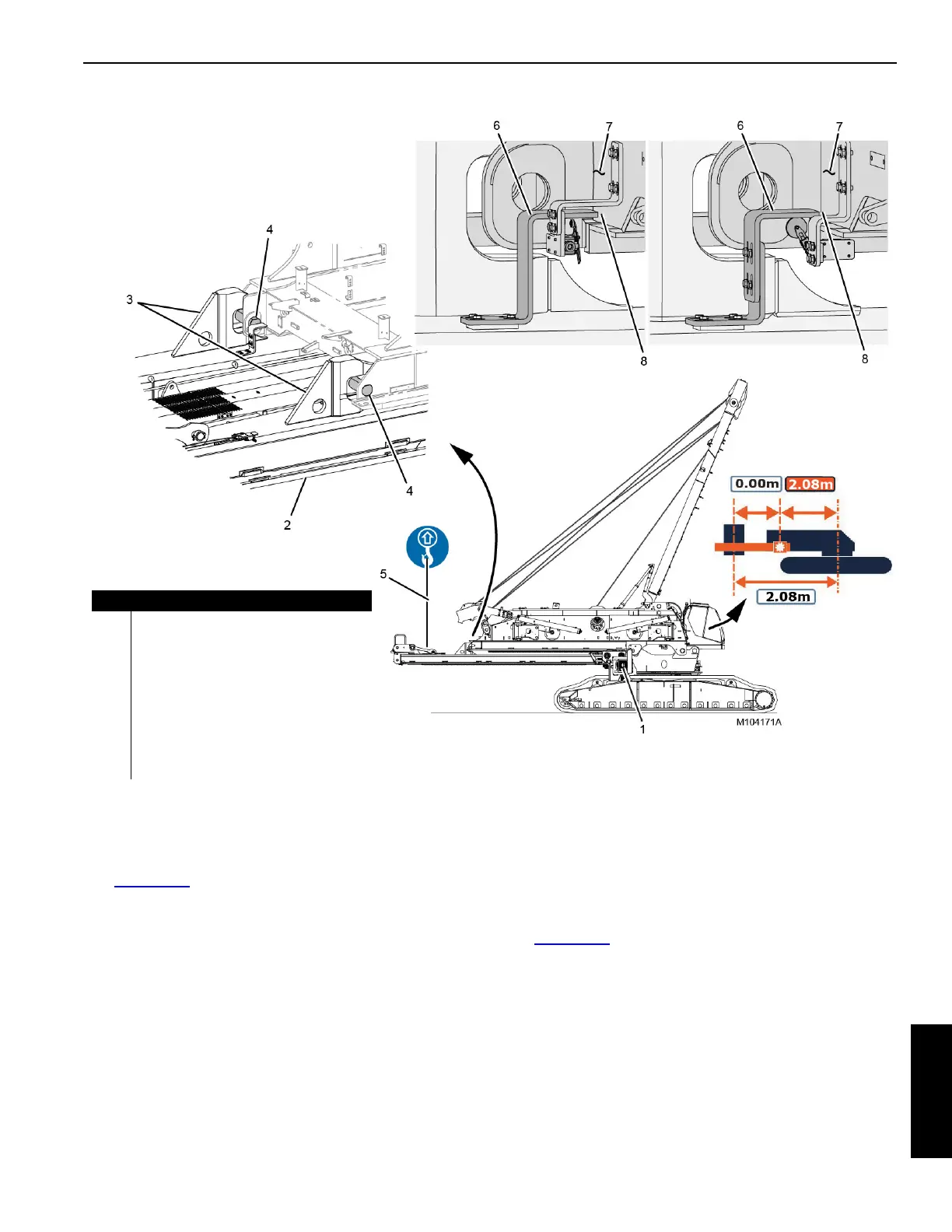
See Figure 6-10 for the following procedure.
Adjust the beam limit switches during VPC-MAX assembly
when the beam is in the following position:
- The rear of the VPC-MAX beam is supported by
pendants (5) from the assist crane.
- The live mast configuration is selected in the RCL/
RCI display.
- The actuator (1) is forward at the minimum
working position. The VPC-MAX calibration
screen in the cab should read 2.08 as shown in
View B.
- The VPC-MAX
beam hooks (3, View C) should be
positioned directly over the pins (4) at the rear of the
rotating bed.
Positioning the Beam-on-Hook Tripping
Brackets
See Figure 6-10 for the following procedure.
1. Loosen the mounting bolts that secure the beam-on-
hook tripping brackets (6, View A) to the beam (2).
2. Once the actuator (1) is driven forward to the minimum
working position, adjust the brackets to the clearance (8,
View A) between the ends of the brackets and the rear of
the rotating bed (vertical plate, not the bottom horizontal
plate).
3. Securely tighten the mounting bolts.
View B
View C
FIGURE 6-10
View A
PAST
View A
CURRENT
Item Description
1 Actuator
2 VPC-MAX Beam
3 Hook (qty 2)
4Pin (qty 2)
5 Pendants from Assist Crane
6 Beam-on-Hook Tripping Bracket (qty 2)
7 Rotating Bed
8 45-55 mm (1-25/32 to 2-5/32 in)

 Loading...


