SET-UP AND INSTALLATION MLC650 VPC-MAX™ OPERATOR MANUAL
4-38
Published 04-06-18, Control # 231-14
Connecting the Electrical Cables
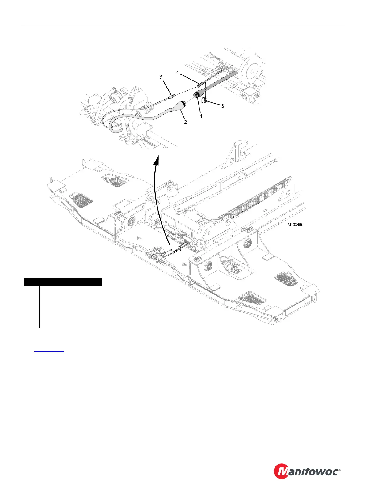
See Figure 4-36 for the following procedure.
1. Remove the dust caps from the plugs.
2. Connect electrical plug WVB1 (1) from the VPC-MAX
beam to electrical plug WVT1-P1 (2) on the
counterweight tray.
3. Remove the terminating resistor (3) from electrical plug
WVB2 (4) on the beam and mate the resistor to the
provided dust cap.
4. Connect electrical plug WVB2 on the beam to electrical
plug WVT2-P1 (5) on the tray.
Positioning the Counterweight Tray
Using the remote control, slowly activate the drive pinions.
Watch each side to ensure the teeth mesh properly. Stop
when the first rack tooth is in full mesh with the pinion.
It is possible that only one pinion will turn prior to engaging
the rack.
FIGURE 4-36
Item Description
1 Electrical Plug WVB1
2 Electrical Plug WVT1-P1
3 Terminating Resistor
4 Electrical Plug WVB2
5 Electrical Plug WVT2-P1

 Loading...


