Manitowoc Published 04-06-18, Control # 231-14 4-77
MLC650 VPC-MAX™ OPERATOR MANUAL SET-UP AND INSTALLATION
Adjusting the Fixed Mast and Beam Position
See Figure 4-65 for the following procedure.
1. For this procedure, the counterweight tray must be in the
minimum working position Figure 4-38 on page 4-40
and fixed mast configuration must be selected in the
RCL/RCI Display.
NOTE: During boom assembly, the mast straps should be
in tension, and the counterweight straps should be
slack. This condition remains from attaching the
counterweight straps.
The beam should still be supported by the beam
hooks at this point. The counterweight tray should
be at the minimum working position. However, for
some boom lengths, partial counterweight may be
required to accomplish this procedure.
2. Once the boom is fully assembled and ready to be
raised, pay out on drum 4 and haul in on drum 5 to raise
the beam into position.
NOTE Paying out wire rope from Drum 4 decreases the
boom suspension tension. Hauling in wire rope on
Drum 5 increases the boom suspension tension.
During fixed mast raising and lowering, the crane
control system may slow down either Drum 4 or
Drum 5 to maintain the constant target tension
specified in Table 4-3
.
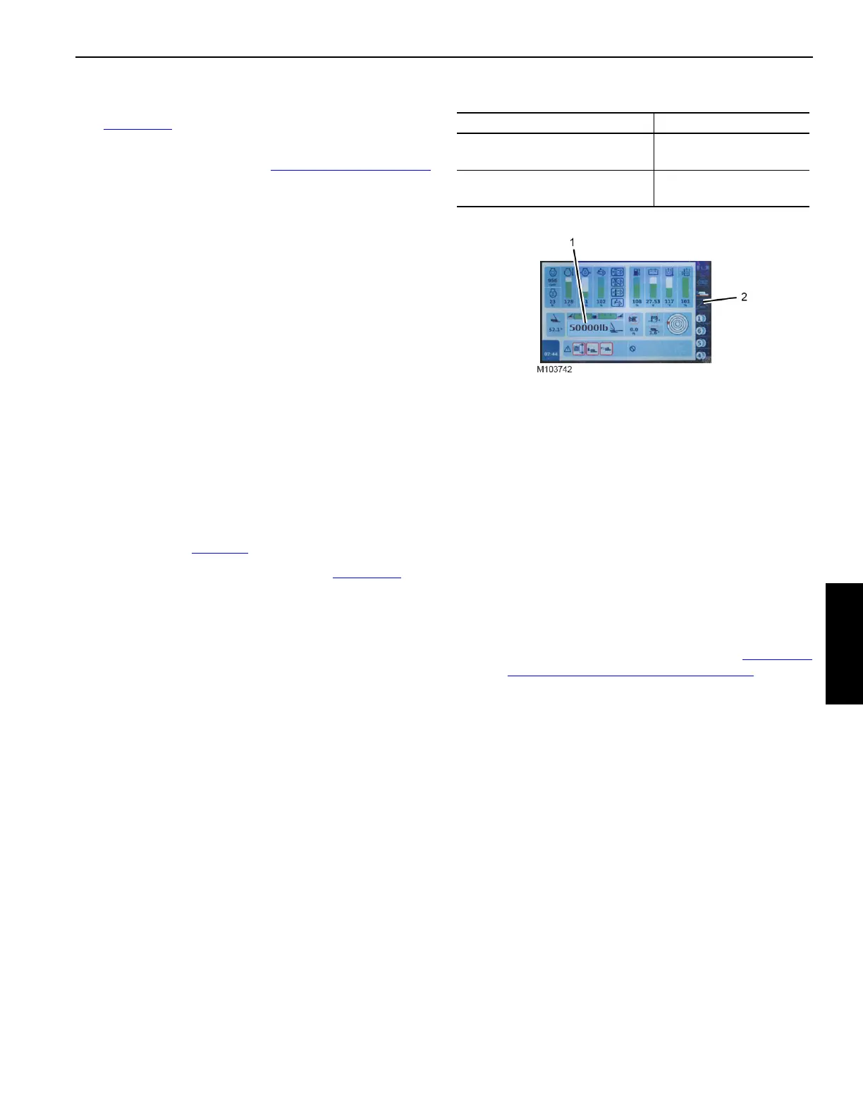
The left side mast strap tension (1, Figure 4-66
) can
be monitored in the Crane Status Bar of the Main
Display (2).
Table 4-3 Target Mast Tension
3. Make sure the counterweight straps are in tension and
the beam hooks are just off the rotating bed pins.
NOTE: As the counterweight strap tension increases, the
backhitch load changes rapidly.
4. Continue raising the beam until the top of the machined
surface (3), indicated by the arrow decal (4) on the beam
hook, is aligned with the center of the green area of the
alignment decal (5), located on the stop block (6)
mounted to the rotating bed.
5. Prepare to raise the boom:
• Enter the desired boom and jib configuration and
select the proper capacity chart in RCL/RCI display.
• Perform the pre-raising checks. See “Performing
Pre-Raising Boom Checks”, on page 4-79.
Type of Fixed Mast Stops Target Tension
Passive (no hydraulic lines to
fixed mast stop cylinders)
22,7 ± 2,0 t
(50,000 ± 4,400 lb)
Active (two hydraulic lines to
each fixed mast stop cylinder)
29,1 ± 2,0 t
(64,200 ± 4,400 lb)

 Loading...


