SET-UP AND INSTALLATION MLC650 VPC-MAX™ OPERATOR MANUAL
4-112
Published 04-06-18, Control # 231-14
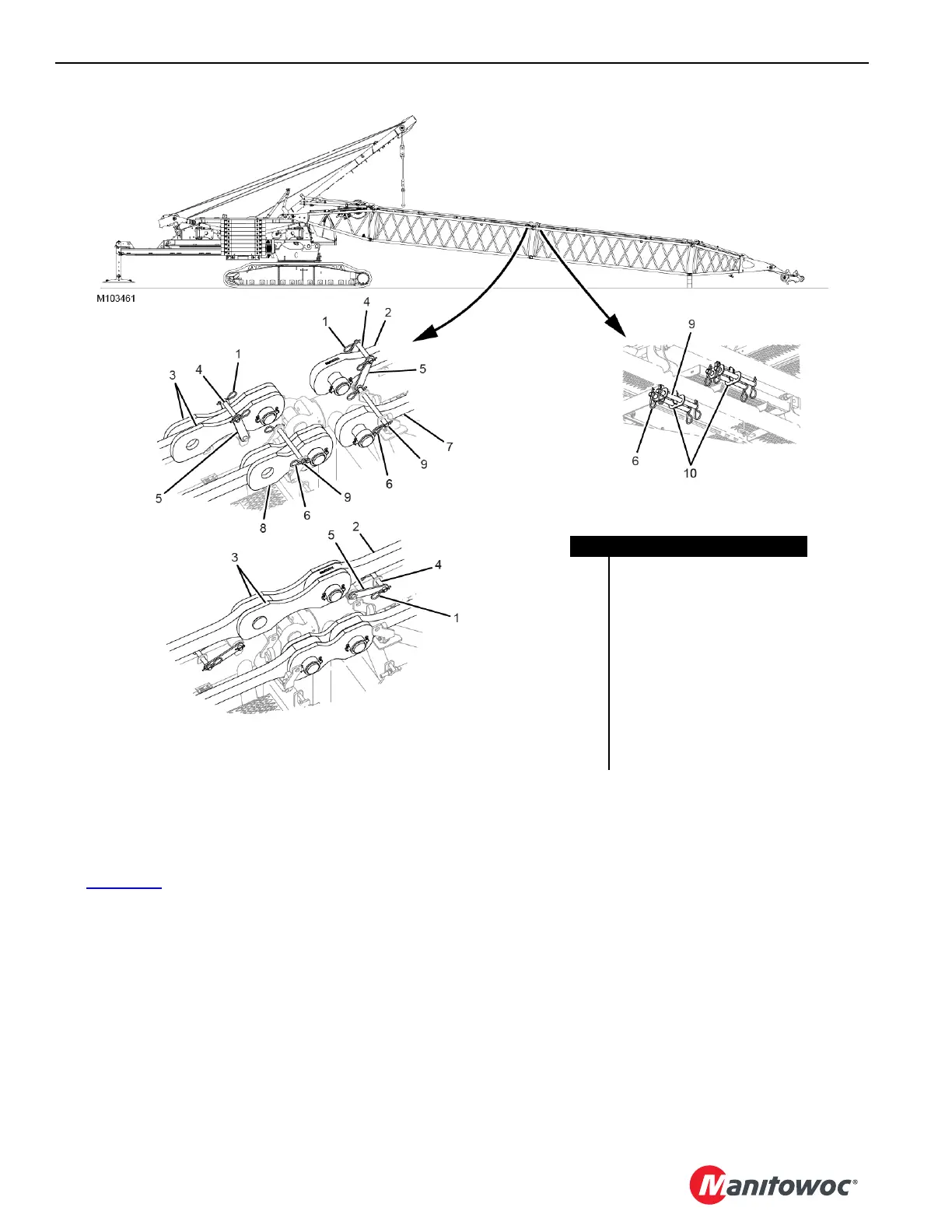
Disconnecting the First Insert and Second Insert
Straps
See Figure 4-93 for the following procedure.
1. Disconnect the straps from the links in the working
position.
2. Remove the hair pin cotters (1) from the VPC-MAX
beam strap (2) and VPC-MAX
link (3) retaining pins (4).
3. Make sure the strap and links are in the stored position.
4. Remove the retaining pins and rotate the retaining pin
brackets (5) from the working position to the stored
position.
5. Install the retaining pins and hair pin cotters to the
brackets in the stored position.
6. Remove the hair pin cotters (6) from the live mast
strap (7) and live mast link (8) retaining pins (9).
7. Make sure the strap and links are in the stored position.
8. Remove the retaining pins from the brackets (10) and
install them in the stored position.
NOTE: Four pins are shown, two for each side.
9. Install the hair pin cotters to the retaining pins.
10. Repeat this process for the other side of the inserts.
FIGURE 4-93
STORED POSITION
WORKING POSITION
Item Description
1 Hair Pin Cotter (qty 8)
2 VPC-MAX Beam Strap (qty 2)
3
VPC-MAX
Link (qty 4)
4 Retaining Pin (qty 4)
5 Retaining Pin Bracket (qty 8)
6 Hair Pin Cotter (qty 8)
7 Live Mast Strap (qty 2)
8 Live Mast Link (qty 4)
9 Retaining Pin (qty 4)
10 Bracket (qty 2)
WORKING POSITION