Manitowoc Published 04-06-18, Control # 231-14 4-37
MLC650 VPC-MAX™ OPERATOR MANUAL SET-UP AND INSTALLATION
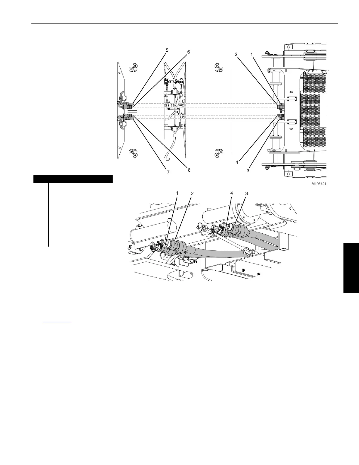
Connecting the Hydraulic Hoses
See Figure 4-35 for the following procedure.
1. Remove the four hydraulic hoses (1–4) from the stored
position.
2. Connect the hydraulic hoses on the VPC-MAX
beam to
the couplers (5–8) on the counterweight tray.
NOTE: The hoses and the corresponding couplers are
tagged with numbers. Match the numbers to
ensure proper hose connection.
FIGURE 4-35
Item Description
1 Hydraulic Hose Number 31
2 Hydraulic Hose Number 32
3 Hydraulic Hose Number 33
4 Hydraulic Hose Number 34
5 Coupler Number 31
6 Coupler Number 32
7 Coupler Number 33
8 Coupler Number 34
STORED POSITION