SET-UP AND INSTALLATION MLC650 VPC-MAX™ OPERATOR MANUAL
4-36
Published 04-06-18, Control # 231-14
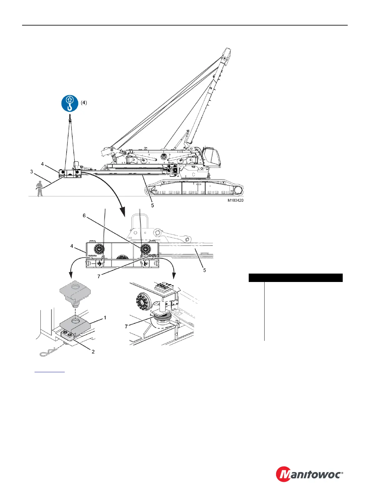
See Figure 4-34 for the following procedure.
4. Remove the large main stop blocks (1). Do not remove
the small bolt-on stop blocks (2).
5. Using the assist crane and the taglines (3), position the
counterweight tray (4) at the back of the VPC-MAX
beam (5) so the front (vertical) rollers (6) contact the
roller wear plates.
6. Adjust (lower) the tray with the assist crane so the tray is
nearly horizontal.
7. Pull the tray onto the beam until the first set of side
rollers (7) on the tray contact the lead-in area on the
sides (edges) of the beam.
8. Using the assist crane and the taglines, slowly draw the
tray farther onto the beam until the rear (vertical) rollers
contact the wear plates.
During this process, the rear rollers contact and roll over
the small bolt-on stop blocks.
FIGURE 4-34
Item Description
1 Large Main Stop Block (qty 2)
2 Small Bolt-on Stop Block (qty 2)
3 Tagline (qty 4)
4 Counterweight Tray
5 VPC-MAX Beam
6 Front (vertical) Roller (qty 2)
7 Side Roller (qty 2)

 Loading...


