Manitowoc Published 04-06-18, Control # 231-14 4-11
MLC650 VPC-MAX™ OPERATOR MANUAL SET-UP AND INSTALLATION
ASSEMBLING THE VPC-MAX
Preparing the Crane
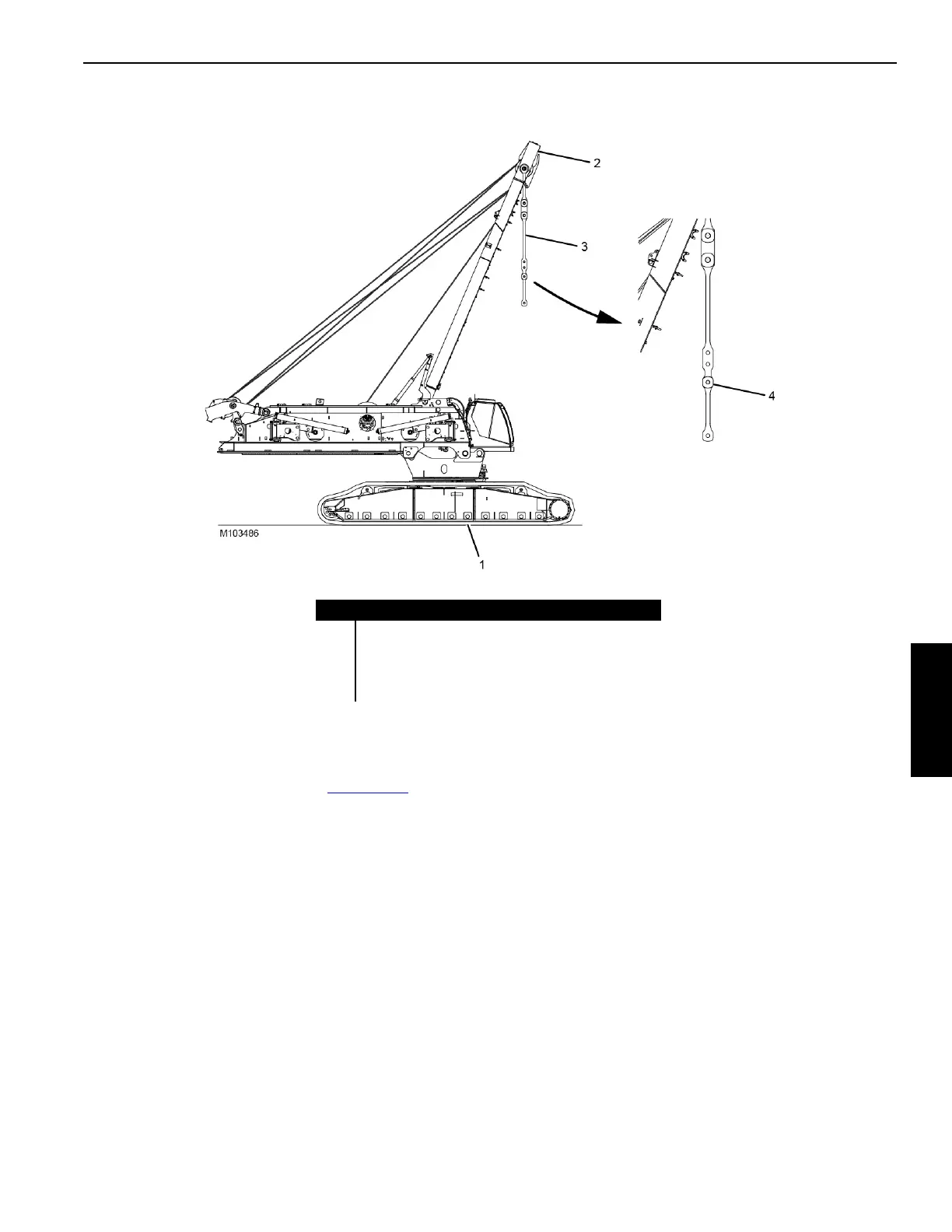
Prior to assembling the VPC-MAX, the MLC650 must be
assembled to the extent shown in Figure 4-13. Refer to
Section 4 of the Crane Operator Manual for crane assembly
instructions.
• Makes sure the live mast arms are fully raised.
• Position the live mast at 111.6° minimum.
• Make sure the live mast straps (3) are connected via
Hole A (4), which is the “longest” hole
If the crane is already fully assembled and rigged with a
boom or a boom and jib, proceed as follows:
1. Lower the boom (and jib) to the ground. See Section 4 of
the Crane Operator Manual or the Luffing Jib Operator
Manual for lowering instructions.
2. Disconnect the boom from the boom butt. See Section 4
of the Crane Operator Manual for instructions.
3. Disconnect the boom butt from the crane. See Section 4
of the Crane Operator Manual for instructions.
4. Remove the counterweight boxes and tray from the
crane. See Section 4 of the Crane Operator Manual for
instructions.
Item Description
1 MLC650 Upperworks and Lowerworks Assembled
2 Live Mast (111.6° minimum)
3Live Mast Straps
4 Hole A
FIGURE 4-13

 Loading...


