Manitowoc Published 04-06-18, Control # 231-14 4-17
MLC650 VPC-MAX™ OPERATOR MANUAL SET-UP AND INSTALLATION
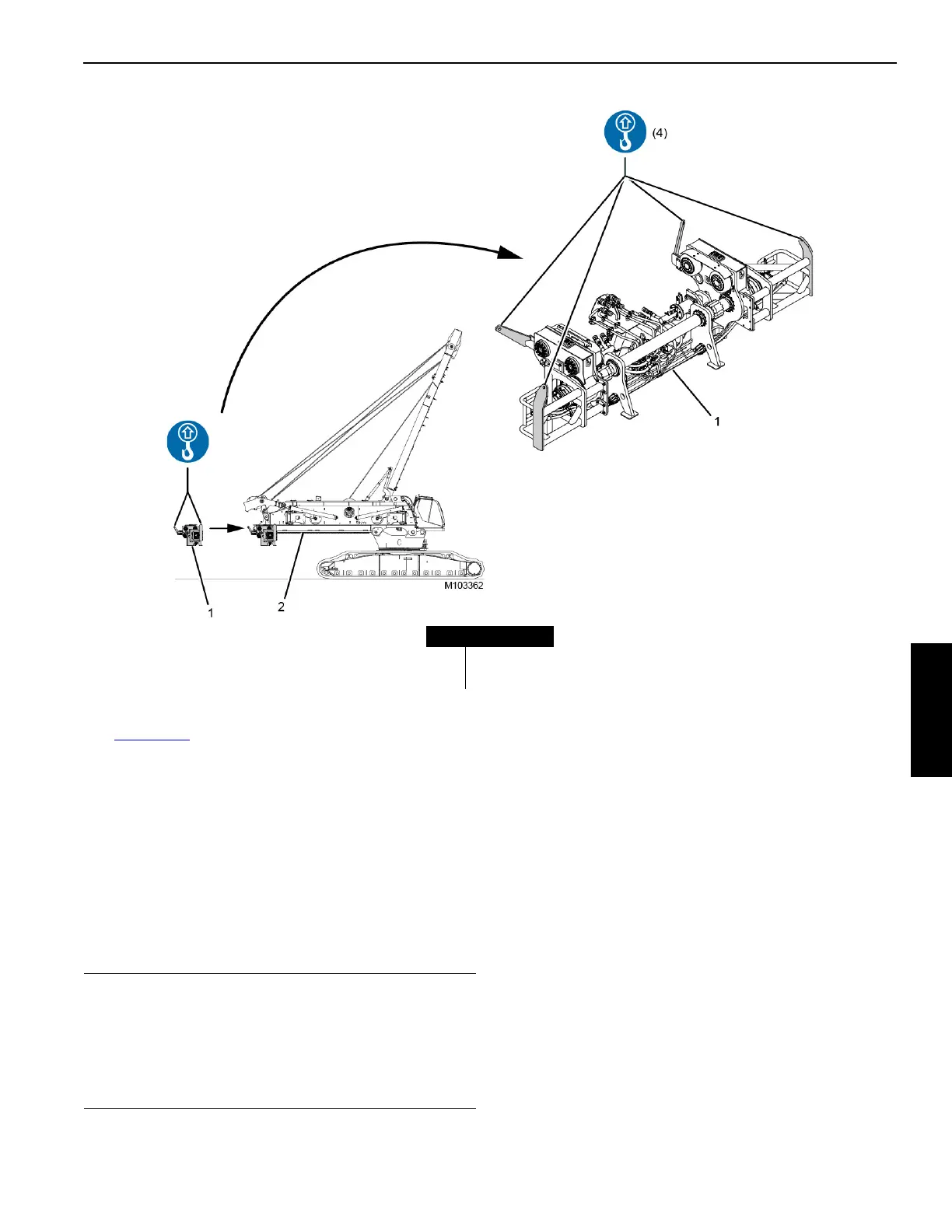
See Figure 4-19 for the following procedure.
2. Using the plates and pendants, attach the actuator (1) to
the assist crane.
NOTE: Any additional rigging used between the assist
crane hook block and plates must not exceed
3,6 m (12 ft) in length. The actuator should hang at
a 2° angle with the rear rollers higher than the front
rollers.
3. Have assistants use the taglines to help control the
movement of the actuator and to help guide it onto the
rotating bed.
4. Using the assist crane, position the actuator at the rear
of the rotating bed (2) so the front (vertical) rollers
contact the roller wear plates.
5. Using the assist crane, adjust the actuator to be
horizontal.
6. Using the assist crane, draw the actuator onto the
rotating bed to a point where the side rollers on the
actuator contacting the sides (edge) of the rotating bed.
Aligning the Actuator
Precise actuator alignment is required in order to install the
actuator beyond the point where the side rollers first contact
the rotating bed.
To properly align the actuator to the rotating bed, use the
assist crane to slowly draw the actuator farther onto the
rotating bed until the rear (vertical) rollers contact the wear
plates.
During this process, the rear rollers contact and roll over the
small rear bolt-on stop blocks.
FIGURE 4-19
Item Description
1Actuator
2 Rotating Bed
CAUTION
Equipment Damage!
The top of the actuator can be damaged if it is lifted too
high.
Make sure the rollers on the actuator maintain contact
with the roller wear plates.

 Loading...


