SET-UP AND INSTALLATION MLC650 VPC-MAX™ OPERATOR MANUAL
4-128
Published 04-06-18, Control # 231-14
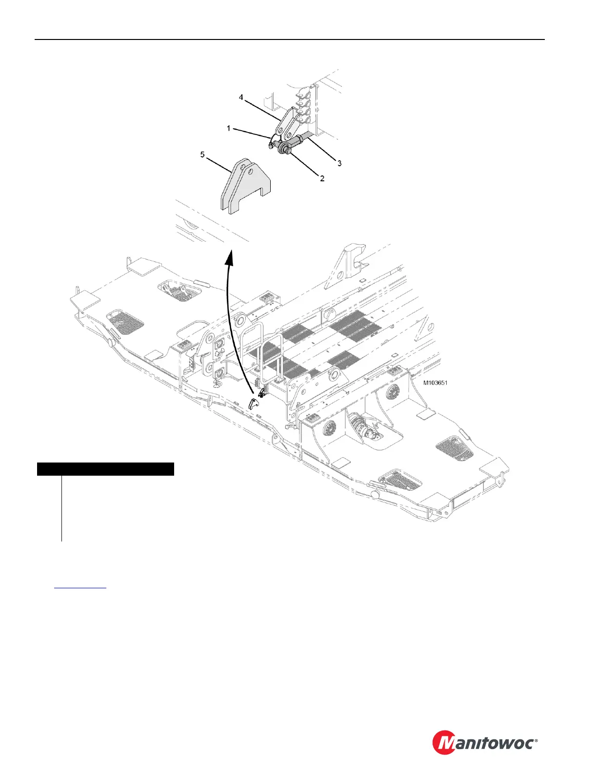
Detaching the Connecting Link
See Figure 4-107 for the following procedure.
1. Using the remote control, drive the counterweight tray
back another 226 mm (8.898 in).
2. Remove the locking pin (1) and retaining pin (2) from the
connecting link (3).
3. Remove the connecting link from the working position in
the counterweight tray bracket (5).
4. Adjust the slide and/or tray position to align the
connecting link with the VPC-MAX beam bracket (4).
5. Install the retaining pin and hair pin cotter to secure the
connecting link in the stored position in the beam
bracket.
FIGURE 4-107
Item Description
1 Locking Pin
2 Retaining Pin
3 Connecting Link
4 VPC-MAX Beam Bracket
5 Counterweight Tray Bracket

 Loading...


