Home
Manitowoc
Construction Equipment
VPC-MAX MLC650
Manitowoc VPC-MAX MLC650 User Manual
5
of 1
of 1 rating
234 pages
Give review
Manual
Specs
To Next Page
To Next Page
To Previous Page
To Previous Page
Loading...
SET-UP AND INSTALLATION
MLC650 VPC-MAX™ OPERA
T
OR MANUAL
4-50
Published 04-06-18, Control # 231-14
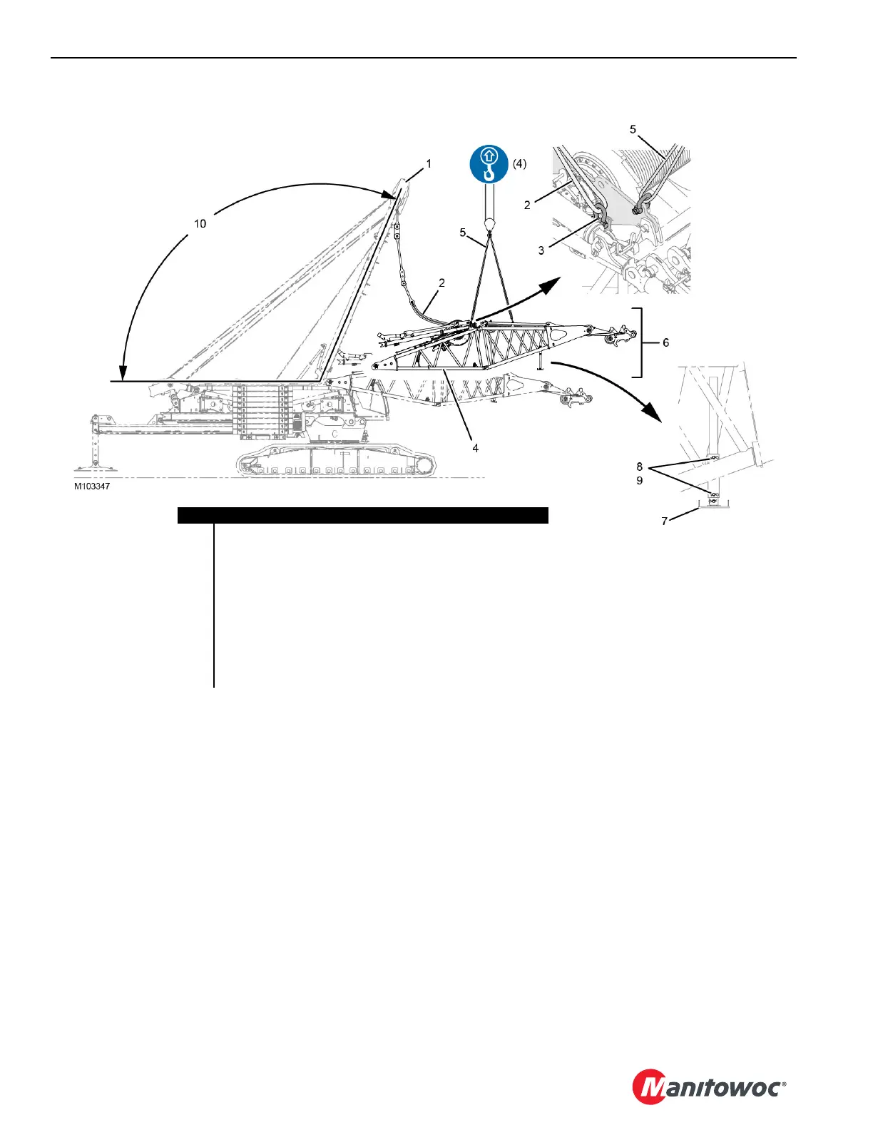
FIGURE
4-45
Item
Desc
ription
1L
i
v
e
M
a
s
t
2
SL 1
Sling – 3,30
m (10.83
ft), 45
360
kg (100,000
lb) (qty 2)
3
SH 2
Shackle – 17
t (18.70
USt
) (qty 2)
4F
i
x
e
d
M
a
s
t
B
u
t
t
5
SL 6
Sling (qty 4, already at
tached)
6
Fixed
Mast Transpor
t Packag
e
7
Support Pedest
al (qty 2)
8
Hair Pin Cotter (qty 8)
9
Retaining
Pin (qty 4)
10
107° to1
13° Angle
Vie
w A
Vie
w
B
107
109
Table of Contents
Default Chapter
5
Table of Contents
5
Section 1
11
Crane Data
11
Crane/Attachment Identification
11
Crane Orientation
11
Outline Dimensions
11
Weights of Components
11
Identification of VPC-MAX Components
11
English and Metric Conversions
14
Direct Conversion
14
Inverse Conversion
14
Change of Ownership Registration
15
Manitowoc Dealer
15
Section 2
17
Continuous Innovation
19
Nameplates and Decals
19
Safety Messages
19
General
19
Safety Alert Symbol
19
Signal Words
19
Symbol Identification
19
Safety and Information Signs
21
Maintaining Signs
21
Ordering Signs
21
Crane Access Points
24
General
24
Getting on or off Crane
24
Personal Fall-Protection
25
Operator Manual/Capacity Chart Storage
26
General
26
Storing Manuals
26
Safe Operating Practices
27
General
27
Read Operator Manual
27
Operator Qualifications
27
Operator Conduct
27
Handling Load
29
Size of Load
29
Attaching Load
29
Lifting/Moving Load
30
Multiple Load Line Operation
31
Signals
32
Holding Load
32
Safety Devices
33
Operational Aids
33
Category 1 Operational Aids
33
Category 2 Operational Aids
34
Assembling, Disassembling, or Operating Crane Near Electric Power and Transmission Lines
35
Electrocution Hazard
35
Set-Up and Operation
35
Electrocution Hazard Devices
36
Electrical Contact
36
Refueling
37
Fire Extinguishers
37
Accidents
37
Safe Maintenance
37
Maintenance Instructions
37
Safe Maintenance Practices
37
Environmental Protection
39
Boom Disassembly Safety
41
General
41
Location
41
Pin Removal
41
Disassembly Precaution
41
Personnel Handling Policy
42
Pedestal/Barge Mounted Cranes
43
Pedestal Mounted Crane
44
Barge Mounted Crane
44
Definition
44
Examples
44
Capacity Charts for Barge Mounted Crane
45
Shock Loading Caused by Barge Dynamics
45
Operation on Barge
45
Barge Mount Definitions
46
Inspection of Barge-Mounted Crane
46
Transporting Crane on Barge
46
Section 3
47
Standard Hand Signals for Controlling Crane Operations
50
Operating Controls and Procedures
51
Operating Precautions
51
Auxiliary Frame Assembly
53
Section 4
59
Boom and Jib Assembly Drawings
59
Liftcrane Mast Handling Capacities
59
Optional Attachments
59
General Safety
59
Crane Orientation
59
Assembly and Disassembly Notes
59
Assembly and Disassembly Area
60
Accessing Parts
60
Retaining Connecting Pins
60
Crane Weights and Shipping Data
60
Personal Fall-Protection
61
Handling Components
61
Assist Crane Requirements
62
Parts Box
62
Hydraulic Hose Identification
64
Connecting/Disconnecting Hydraulic Hoses and Electric Cables
64
Hose and Cable Cleanliness
64
Hydraulic Quick Disconnect Lubrication
65
Pin and Connecting Hole Cleanliness
65
Tightening Hydraulic Couplers
65
Setup Mode
66
Auxiliary Hydraulic System
66
Hand-Held Pin Puller
66
Swing Limits
68
Assembling the VPC-MAX
69
Preparing the Crane
69
Checking the Electrical System
71
Checking the Hydraulic System
71
Checking the Gear Boxes
71
Preparing for Actuator Installation
72
Removing the Large Main Stop Blocks
73
Installing the Actuator
74
Handling the Actuator
74
Aligning the Actuator
75
Connecting the Hydraulic Hoses
76
Testing the Actuator
78
Attaching the Connecting Link
81
Installing the Large Main Stop Blocks
81
Checking Limits and Calibrating the VPC-MAX Actuator
81
Installing the VPC-MAX Beam
83
Connecting the Electrical Cables
88
Drawing the VPC-MAX Beam Onto the Rotating Bed
89
Installing the Counterweight Tray
93
Handling the Tray
93
Connecting the Hydraulic Hoses
95
Connecting the Electrical Cables
96
Positioning the Counterweight Tray
96
Attaching the Connecting Link
97
Installing the Large Main Stop Blocks
97
Detaching the Assist Crane
97
Calibrating the Counterweight Tray
99
Installing the Auxiliary Frame Assembly
100
Removing the Counterweight Boxes from the Trailer
103
Installing the Counterweight Boxes
103
Assembling the Fixed Mast
106
Installing the Live Mast Lifting Slings
106
Installing the Fixed Mast Transport Package
107
Connecting the Fixed Mast Hydraulic Hoses Electrical Cable
110
Disconnecting the Fixed Mast Top from the Fixed Mast Butt
110
Installing the Fixed Mast Inserts
113
Installing the Fixed Mast Top
114
Connecting the Mast Straps
118
Configuring the Fixed Mast in the RCL/RCI Display
119
Raising the Mast Stops
123
Preparing the Equalizer
123
Installing the Boom Assembly
124
Assembling the Remaining Boom Sections
125
Connecting the Boom Straps
125
Moving the Equalizer to the Equalizer Rails
127
Closing the Boom Sections Using an Assist Crane
129
Closing the Boom Sections Using the Fixed Mast
131
Finishing Boom Assembly
131
Connecting Equalizer Links to Boom Straps
133
Raising Fixed Mast to Operating Position
133
Adjusting the Fixed Mast and Beam Position
135
Performing Pre-Raising Boom Checks
137
Raising the Boom
137
Wire Rope Installation
140
Wire Rope Specifications
140
Wire Rope Storage
140
Seizing and Cutting Wire Rope
140
Anchoring Wire Rope to Drum
141
Winding Rope Onto Drum
141
Anchoring Wire Rope to Wedge Socket
145
Anchoring Wire Rope to Button Socket
145
Pad Eye Usage for Wire Rope Reeving
147
Breaking in Wire Rope
147
General
147
Safety
147
Rigging Winch Operation
148
Selecting Rigging Winch Mode
148
Operating Rigging Winch
149
Free-Spool Operation
149
Power Operation
149
Load Line Reeving
151
Guide Sheaves and Drums
151
Load Block Identification
151
Duplex Hook
151
Wire Rope Specifications
151
Load Block Reeving
151
Dead End Locations
152
Inspecting the VPC and VPC-MAX Roller Paths
152
Auxiliary Frame Operating Positions
155
Shipping Crane Components
156
Disassembling the VPC-MAX
157
Lowering the Boom
157
Detaching the Counterweight Straps
157
Lowering the Fixed Mast to the Boom Handling Position
159
Detaching the Equalizer Links from the Boom Straps
159
Disconnecting the Boom Straps
159
Opening the Boom Sections Using the Fixed Mast
161
Opening the Boom Sections Using an Assist Crane
163
Disconnecting the Equalizer from the Equalizer Rails
163
Disassemble the Boom Assembly
163
Removing the Partial Boom Assembly
164
Attaching the Equalizer to the Fixed Mast Top
165
Lowering the Mast Stops
167
Disconnecting the Mast Straps
167
Disconnecting the First Insert and Mast Butt Straps
168
Disconnecting the Live Mast Straps from the First Insert
169
Disconnecting the First Insert and Second Insert Straps
170
Disconnecting the Mast Top and Second Insert Straps
171
Disassembling the Fixed Mast
172
Installing the Live Mast Lifting Slings
172
Removing the Fixed Mast Top
173
Removing the Fixed Mast Inserts
175
Attaching the Fixed Mast Top to the Butt
175
Positioning the Live Mast
181
Removing the Counterweight Boxes
181
Placing the Counterweight Boxes on the Trailer
181
Removing the Auxiliary Member
182
Removing the Counterweight Tray
185
Handling the Counterweight Tray
185
Removing the Large Main Stop Blocks
185
Detaching the Connecting Link
186
Moving Tray Pinions out of Mesh
187
Removing the Tray
190
Removing the VPC-MAX Beam
191
Detaching the VPC-MAX Beam from the Actuator
197
Removing the Actuator
198
Removing the Large Main Stop Blocks
198
Detaching the Connecting Link
199
Moving the Actuator Pinions out of Mesh
200
Removing the Actuator from the Rotating Bed
203
Installing the Large Main Stop Blocks
204
Section 5
205
Section 6
205
Angle Sensors
211
Drum 5 Boom Hoist
213
Drum 5 Pawl Operation
213
Adjusting the Drum 5 Limit Switch
213
Adjusting the Drum 5 Return Spring
213
Lubricating the Drum 5 Pawl
213
Changing the Drum 5 Oil
214
Adjusting the Drum 5 Pressure Roller
215
Mast Stop
217
Checking the Mast Stop Pressure
217
Checking the Mast Stop Limit Switch
217
VPC-MAX Trolley
219
VPC-MAX Trolley Speed Sensor
219
Adjusting the VPC-MAX Trolley Speed Sensor
219
VPC-MAX Trolley Absolute Encoder
219
Adjusting the VPC-MAX Trolley Absolute Encoder Backlash
219
Adjusting the VPC-MAX Trolley Roller Backlash
220
VPC-MAX Calibration
222
Calibrating the VPC-MAX Actuator
222
Calibrating the Counterweight Tray
222
VPC-MAX Limit Switches
223
Adjusting the Beam Limit Switches
223
Positioning the Beam-On-Hook Tripping Brackets
223
Positioning the Limit Switch Levers
224
Adjusting the Beam up Limit Switches
224
Adjusting the Beam-On-Hook Limit Switches
224
Checking the Beam in and out Limit Switches
227
Checking the Tray in and out Limit Switches
229
Wiring the VPC-MAX Limit Switches
229
VPC and VPC-MAX Roller Path
229
5
Based on 1 rating
Ask a question
Give review
Questions and Answers:
Need help?
Do you have a question about the Manitowoc VPC-MAX MLC650 and is the answer not in the manual?
Ask a question
Manitowoc VPC-MAX MLC650 Specifications
General
Brand
Manitowoc
Model
VPC-MAX MLC650
Category
Construction Equipment
Language
English
Related product manuals
Manitowoc MLC650
360 pages
Manitowoc 14000
270 pages
Manitowoc MLC300
332 pages
Manitowoc MLC100-1
218 pages
Manitowoc Grove YB5515
134 pages
Manitowoc Grove RT890E
24 pages
Manitowoc Grove RT9130E
28 pages
Manitowoc Grove GMK6300L
1004 pages
Manitowoc 14000 2 Series
4 pages
Manitowoc GROVE GMK5150L
1040 pages
Manitowoc 14000 1 Series
6 pages
Manitowoc Grove GMK 5250L
958 pages

 Loading...


