22
model no. 055-6768-8 | contact us 1-800-689-9928
ASSEMBLY
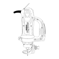
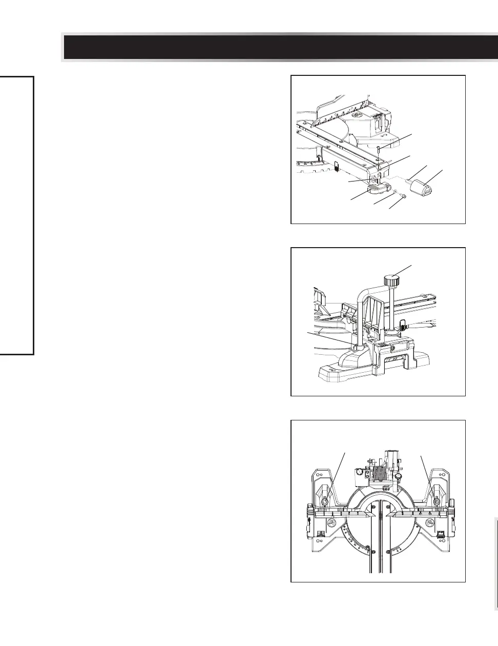
INSTALLING THE BEVEL LOCK HANDLE
(Fig. 3)
• Insert the bevel lock handle (1) onto the
shaft (2) at an approximately angle 30°
below the level as shown in Fig. 3.
• Thread the hex screw (3) through the
washer (4) into the bevel lock handle (1).
• Tighten the screw (4) with the 5 mm
hex wrench.
INSTALLING THE MITRE HANDLE (Fig. 3)
• Insert the mitre handle (5) into the hole in
front of the mitre saw and align the hole (6)
on the mitre handle (5) with the hole (7) in
the front of the table.
• Thread the screw (8) through the hole (7) in
the table into the hole (6) on the mitre
handle (5).
• Tighten the screw (8) with a screwdriver.
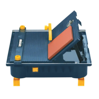
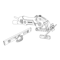
INSTALLING THE HOLD-DOWN CLAMP
ASSEMBLY (Fig. 4, 5)
Place the hold-down clamp assembly (1) in one
of the mounting holes (2) located behind the
fence.
Fig. 3
Fig. 4
8
1
4
3
2
6
7
5
1
2
Fig. 5
2
2
 Loading...