48
model no. 055-6768-8 | contact us 1-800-689-9928
OPERATION
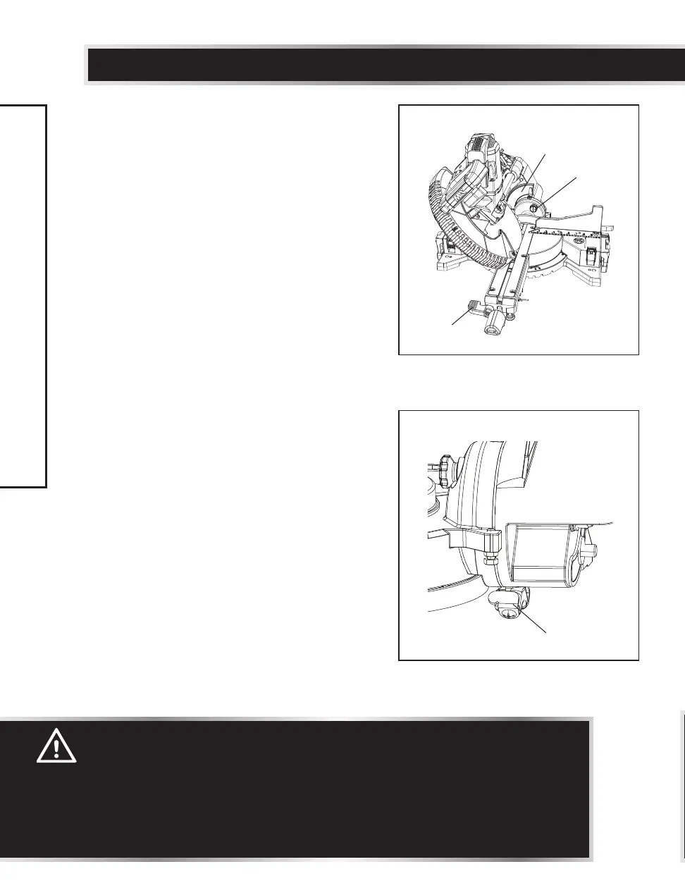
BEVEL CUT (Fig. 41, 42)
• When a bevel cut is required, loosen the
bevel locking handle (1) by turning it
clockwise.
• Tilt the cutting head to the desired angle,
as shown on the bevel scale (2).
• The blade can be positioned at any angle,
from a 90° straight cut (0° on the scale) to
a 45° left bevel. Tighten the bevel locking
handle (1) to lock the cutting head in
position. Positive stops are provided at 0°,
33.9° and 45°.
NOTE: The saw comes with a 33.9° bevel
detent pin for setting up crown molding
cuts when the angle of the walls equals 90°.
• Turn the laser guide on and position the
workpiece on the table for pre-alignment of
cutting.
• For performing 47° bevel cuts, slide the set
plate (4) to the rear of the saw. Slide right
set plate for right side 47° bevel cutting;
slide the left side set plate for left side 47°
bevel cutting. (Fig. 42)
33.9° BEVEL DETENT PIN FOR CROWN
MOLDINGS (Fig. 41)
• Push the bevel detent pin (3) in towards the
rear of the machine.
• Loosen the bevel locking handle (1).
• Rotate the cutting head until the bevel
detent pin (3) stops the bevel angle at
33.9° on the bevel scale (2).
• Tighten the bevel locking handle (1) before
cutting.
WARNING:
• The sliding fence must be fully extended to the left or right when
making bevel cuts. Failure to extend the sliding fence may not allow
enough space for the blade to pass through, which could result in
serious injury. At extreme mitre or bevel angles, the saw blade may
also contact the fence.
• The sliding fence must be fully extended to the left or right when
making a bevel cut.
Fig. 41
2
1
3
Fig. 42
4
 Loading...