44
model no. 055-6768-8 | contact us 1-800-689-9928
OPERATION
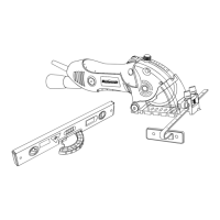
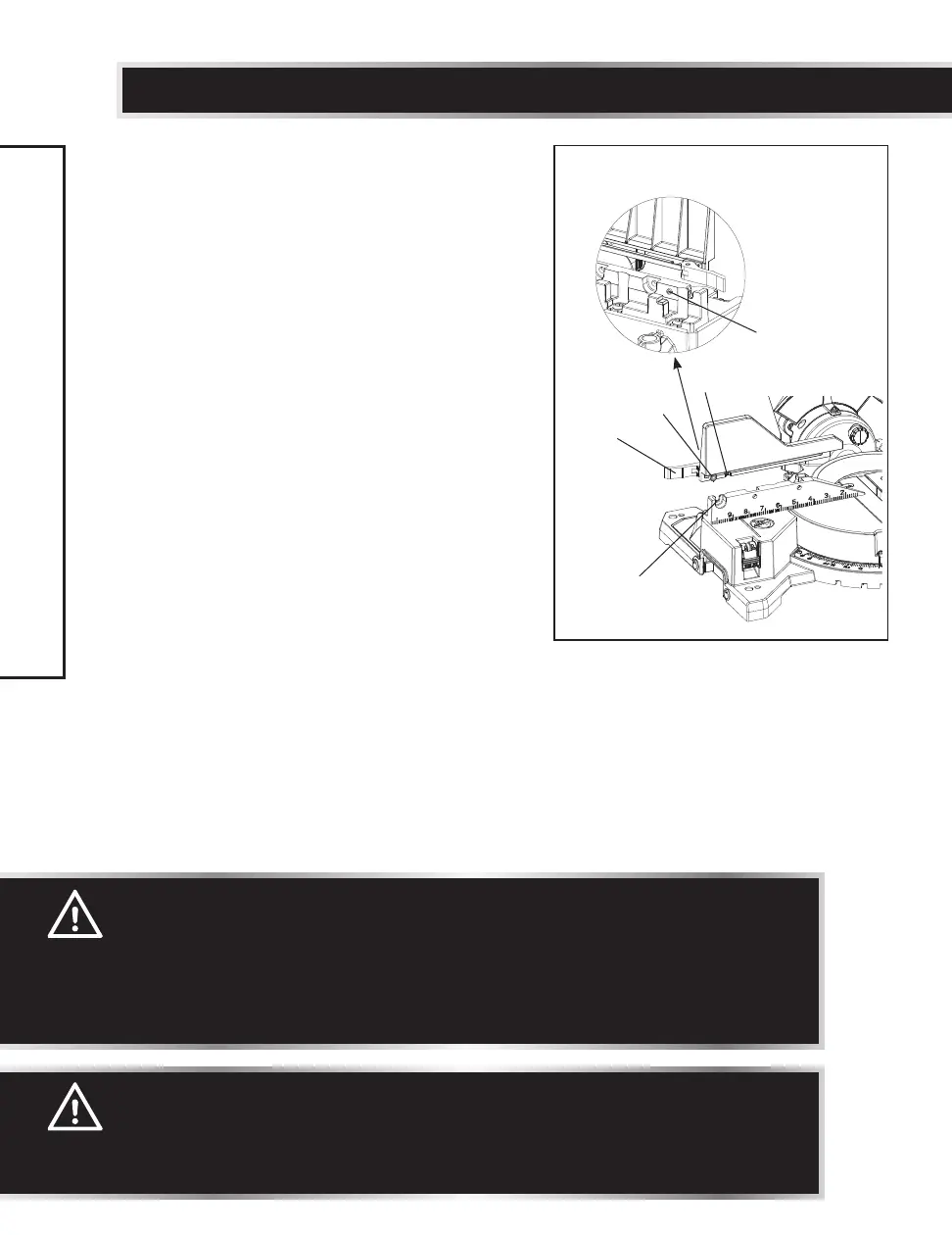
REMOVING OR INSTALLING THE SLIDING
FENCE (Fig. 36)
Removing
• Unlock the fence cam locking lever (1)
by pushing it out towards the rear of the
machine.
• Align the slot (2) with the bolt (3) in the
rear of the fence, and then lift up the sliding
fence to remove it from the saw.
Installing
• Align the slot (2) with the bolt (3) in the
rear of the fence to place the sliding fence
onto the mitre saw fence.
• Slide the fence to align the nut (4) with the
slot (5).
• To lock the sliding fence, push the fence
cam locking lever (1) in towards the front of
the machine.
Fig. 36
5
1
4
2
3
WARNING:
DRY RUN - It is important to know where the blade will intersect with
the workpiece during cutting operations. Always perform a simulated
cutting sequence with the power tool switched OFF to gain an
understanding of the projected path of the saw blade. At some extreme
angles, the left side fence might have to be removed to ensure proper
clearance prior to making the cut.
CAUTION:
The sliding fence must be removed when making any bevel angle cuts
greater than 33.9° in combination with any right or left mitre angle.
The sliding fence also must be removed whenever a 45° bevel angle is
desired with a mitre angle greater than 31.6°.
 Loading...