33
TM
ADJUSTMENTS
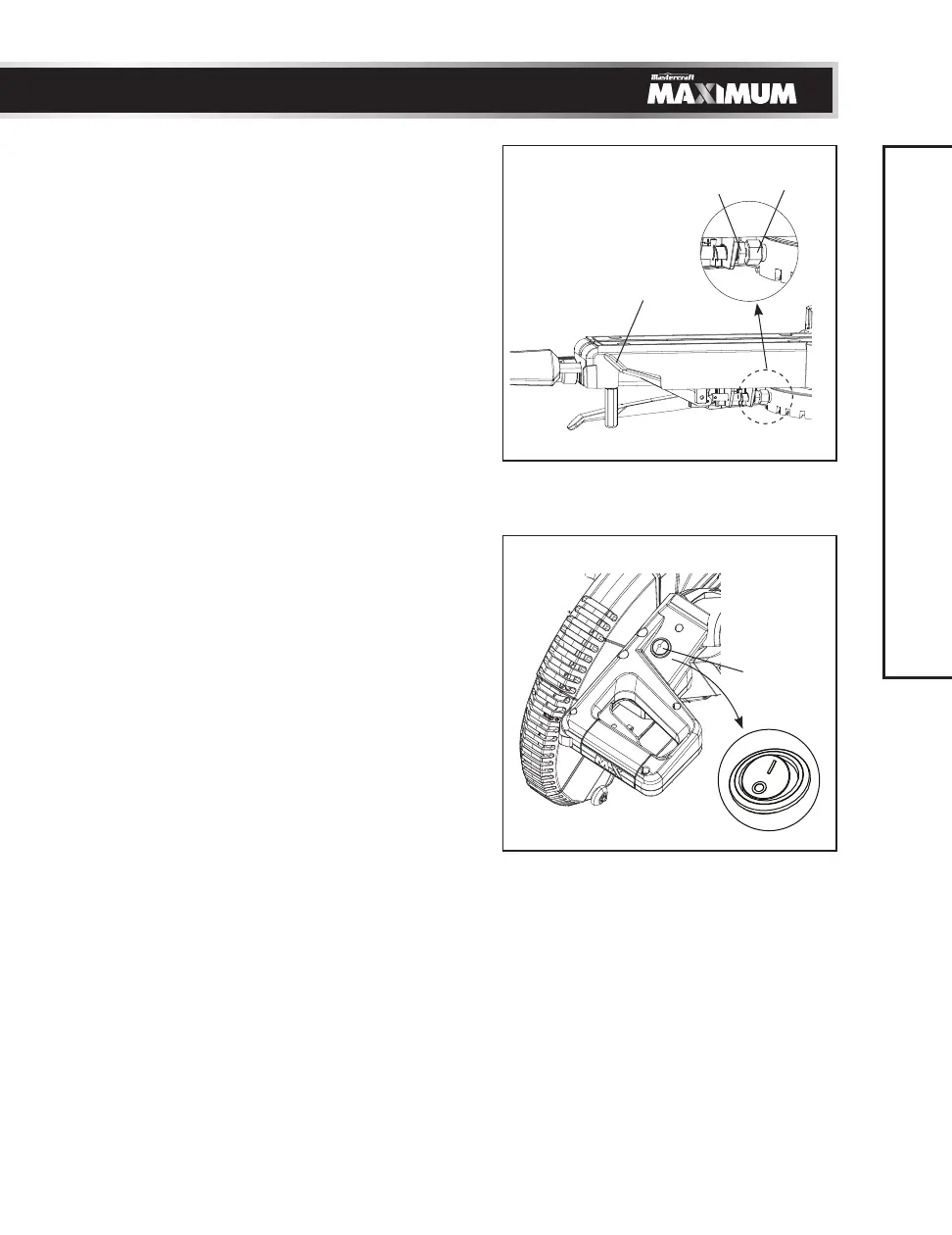
QUICK CAM MITRE LOCKING LEVER
ADJUSTMENT (Fig. 25)
• Press down and lock the quick cam mitre
locking lever (1).
• If the table moves with the quick cam
mitre locking lever in down position, turn
the stop nut (2) to the left using a 13 mm
wrench to extend the locking arm against
the base of the mitre saw.
• Test the quick cam mitre locking lever
to verify it locks the table into position
securely.
• Turn the lock nut (3) to the right to lock the
mitre locking mechanism into place.
TURNING LASER GUIDE ON (Fig. 26)
• To turn laser on, press on/off rocker
switch (1) to “I” position.
• To turn laser off, press on/off rocker
switch (1) to “O” position.
ALIGNING THE LASER GUIDE
The laser beam must always be correctly
aligned with the blade to ensure straight, even
cutting. Your tool is equipped with the laser
cutting guide using a Class IIIa laser beam.
The laser beam will enable you to preview
the saw blade path on the stock to be cut
before starting the mitre saw. This laser guide
is powered by the transformed alternating
current supply directly through the power
lead. The saw must be connected to the power
source and the laser on/off switch must be
turned on for the laser line to show.
Fig. 25
2
3
1
Fig. 26
1
 Loading...