model no. 055-6768-8 | contact us 1-800-689-9928
28
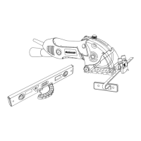
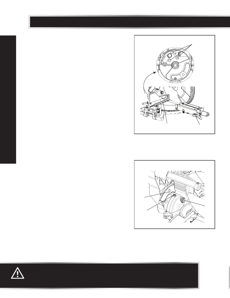
Fig. 15
BEVEL STOP ADJUSTMENT
90° (0°) Bevel Adjustment (Fig. 15, 16)
• Loosen bevel lock handle (1), and tilt the
cutting arm completely to the right while
pushing in the bevel detent pin (3 - Fig. 16)
in against the 0° bevel stop. Tighten the
bevel lock handle (1).
• Place a combination square (2) on the mitre
table with the rule against the table and the
heel of the square against the saw blade.
• If the blade is not 0° to the mitre table,
loosen the three adjustment bolts (6) at the
rear of the saw with a 4 mm hex wrench.
Unlock the bevel lock handle (1) and adjust
the cutting arm.
• Tilt the cutting arm to the right at 90° (0°)
bevel and recheck for alignment.
• Repeat steps above if further adjustment is
needed.
•
Tighten three adjustment bolts (6) and bevel
lock handle (1) when alignment is achieved.
90° Bevel Pointer Adjustment (Fig. 16)
• When the blade is exactly 90° (0°) to the
table, loosen the bevel pointer screws (4)
using a star-head screwdriver.
• Adjust bevel pointer (5) to the “0” mark on
the bevel scale and retighten the screw.
WARNING:
To avoid injury from an accidental start, make sure the switch is in the OFF
position and the plug is not connected to the power source outlet.
Fig. 16
1
6
2
5
4
3
ADJUSTMENTS
 Loading...