6 - 2 6 - 2
MELSEC-Q
6 DATA COMMUNICATION USING THE NON PROCEDURE PROTOCOL
6
6.1 Data Reception from the External Device
This section explains data reception from the external device.
There are two methods for receiving data: the "reception via receive complete code"
for receiving variable length messages, and the "reception via received data count" for
receiving fixed length messages. The receive complete code and received data count
used for data reception can be changed to any setting values chosen by the user using
GX Configurator-SC.
6.1.1 Receiving methods
The following shows the methods for receiving data in any format using the non-
procedure protocol.
There are two methods for receiving data: the "reception via receive complete code"
for receiving variable length messages, and the "reception via received data count" for
receiving fixed length messages. The receive complete code and received data count
used for data reception can be changed to any setting values chosen by the user using
GX Configurator-SC.
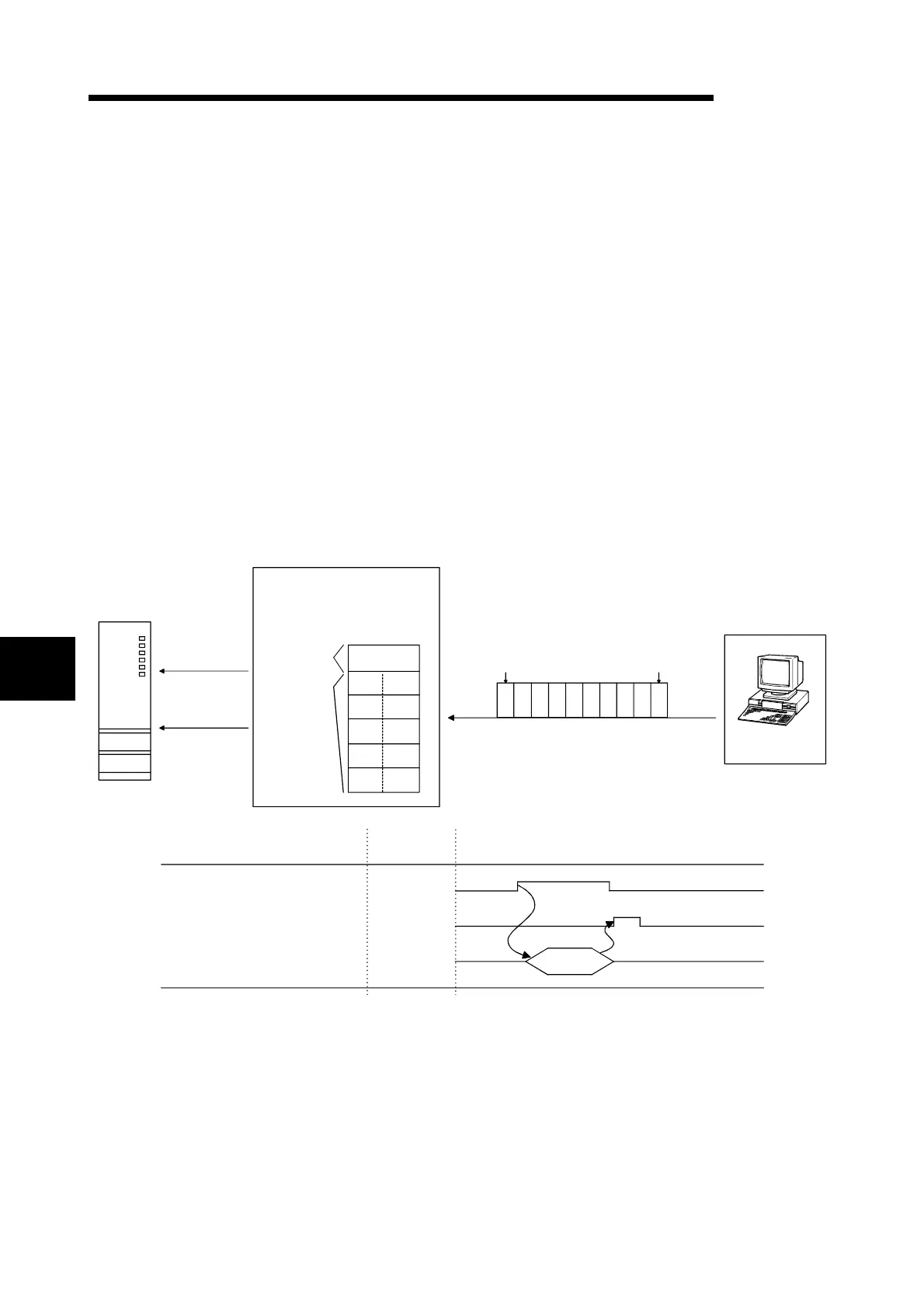
PLC CPU
1)
Reception data
read request
Receiving area
(buffer memory)
Receive data
storage area
Receive data
count storage
area
10
STX
D
F
H
(02
H
)
(48
H
)
(46
H
)
(44
H
)
B
(42
H
)
(0A
H
)
A
(41
H
)
G
(47
H
)
E
(45
H
)
C
(43
H
)
ETX
(03
H
)
(00
H
)
Q series C24
STX A BCDEFGHETX
Head data Receive complete code
(02
H
)(41
H
)(48
H
)(47
H
)(46
H
)(45
H
)(44
H
)(43
H
)(42
H
)(03
H
)
Transmission data
External device
RUN.
ERR.
USER.
BAT.
BOOT.
RS-232
USB
Q25HCPU
MODE.
2) 3)
INPUT
instruction
Description
Reception data read request signal
INPUT instruction complete device
INPUT instruction
CH1/CH2
X3/XA
Control timing
INPUT
1) When data is received from the external device using either "reception via receive
complete code" or "reception via received data count" method, the reception data
read request signal (X3/XA) turns ON.
2) Control data is stored in the device designated with the INPUT instruction.
3) When the INPUT instruction is executed, receive data is read from the reception
area of the buffer memory.

 Loading...