10 - 3 10 - 3
MELSEC-Q
10 TROUBLESHOOTING
[Displays]
1) H/W LED Information Right side (Left side: CH1 information/
Right side: CH2 information)
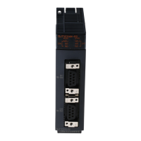
Displays the transmission status and the communications error status
of the Q series C24.
(Displays 201
H
/202
H
of the buffer memory.)
1/0 1/0 1/0 1/0 1/0 1/0 1/0 1/0
SD WAIT
SIO
PRO.
P/S
NEU.
C/N
NAK
ACK.
For system
Buffer memory address 201
H
b15 b7b6b5b4b3b2b1b0
to
(Information of CH1 side)
1: Lit/Communication error
0: not lit/No communication error
b8
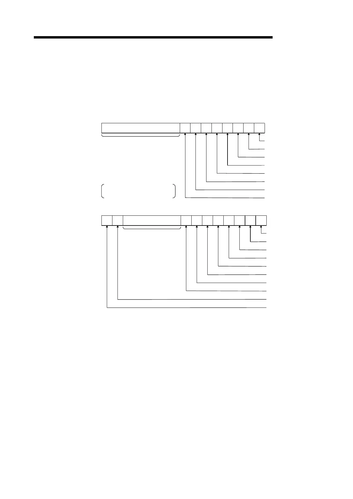
1/0 1/0 1/0 1/0 1/0 1/0 1/0 1/0
SD WAIT
SIO
PRO.
P/S
NEU.
C/N
NAK
ACK.
For system
Buffer memory address 202
H
b15 b7 b6 b5 b4 b3 b2 b1 b0
to
(Information of CH2 side)
1/0 1/0
b14 b13 b8
CH2 ERR.
CH1 ERR.
2) H/W SW Information Parameter
The switch information of the Q series C24 is displayed.
Numbers 1 through 5 correspond to switches 1 through 5 shown in
Section 4.5.2.
(See Section 4.5.2 of the User's Manual (Basic).)

 Loading...