3 - 6 3 - 6
MELSEC-Q
3 SPECIFICATIONS
3.3 RS-422/485 Interface Specifications
The following shows the RS-422/485 interface specification.
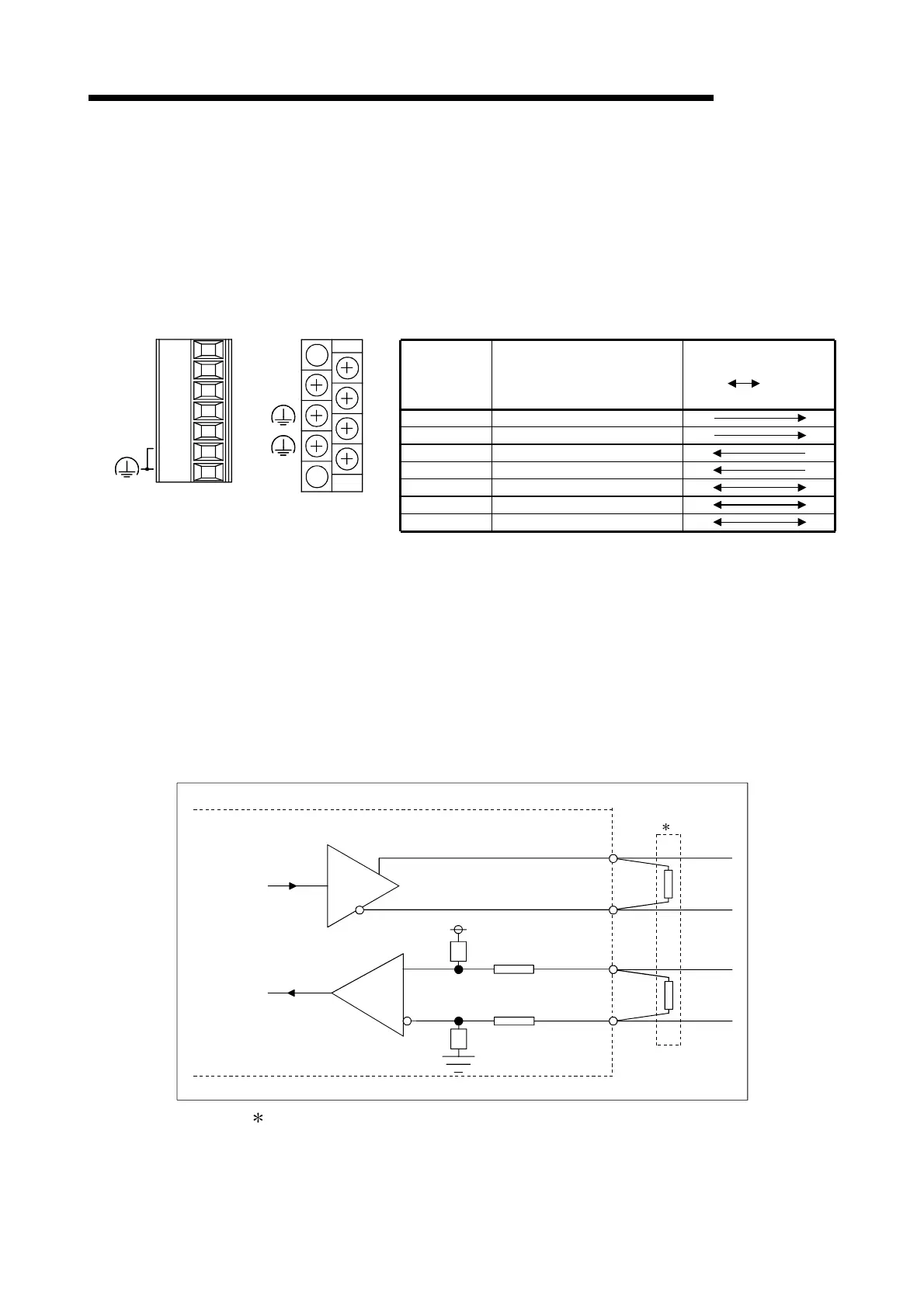
3.3.1 RS-422/485 terminal block specifications
The following shows the specifications of the RS-422 connector and RS-422/485
terminal block that connect to an external device.
Signal
abbreviation
Signal name
Signal direction
C24
External
device
SDA
SDB
RDA
RDB
SG
FG
FG
Send data (+)
Send data (–)
Receive data (+)
Receive data (–)
Signal ground
Frame ground
Frame ground
SG
SDA
SDB
RDA
RDB
SG
RDB
RDA
SDB
(FG)
SDA
QJ71C24N-R4
QJ71C24N
QJ71C24
(FG)
(FG)
(1) The following describes the control signals.
1) SDA, SDB signals
These are signals to send data from the Q series C24 to the external
device.
2) RDA, RDB signals
These are signals for the Q series C24 to receive data from the external
device.
(2) The following shows the function block diagrams.
(RS-422/485 interface)
Send data
SDA
SDB
RDA
RDB
1
+
+
–
–
Receive data
1 The following shows the terminal resistor connection.
Connect the terminal resistor according to Section 4.4.2 or the User's Manual
(Hardware) of the Q series C24 used.

 Loading...