App. - 58 App. - 58
MELSEC-Q
APPENDIX
(GX Developer "Intelligent function module switch setting" setting values recording check
sheet)
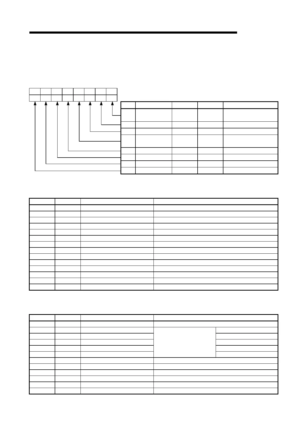
(1) Transmission setting (Enter "0" or "1" in the bit position field)
b7 b6 b5 b4 b3 b2 b1 b0
CH1 side
CH2 side
Bit Description OFF (0) ON (1) Remarks
b0 Operation setting Independent Linked
Always set to OFF on
CH1 side.
b1 Data bit 7 8 Do not include parity bit.
b2 Parity bit No Yes Vertical parity
b3 Odd/even parity Odd Even
Valid only when parity
bit is set to Yes.
b4 Stop bit 1 2 —
b5 Sum check code No Yes —
b6 Write during RUN Prohibit Allow —
b7 Setting modification Prohibit Allow —
(2) Communication rate setting (Enter check marks in the CH1 and
CH2 fields)
CH1 CH2 Setting value Communication speed (unit: bps)
F
H
50
0
H
300
1
H
600
2
H
1200
3
H
2400
4
H
4800
5
H
9600
6
H
14400
7
H
19200
8
H
28800
9
H
38400
A
H
57600
B
H
115200
C
H
230400
(3) Communication protocol setting (Enter check marks in the CH1 and
CH2 fields)
CH1 CH2 Setting value Setting data
0
H
GX Developer connection
1
H
Format 1
2
H
Format 2
3
H
Format 3
4
H
Format 4
5
H
MC protocol
Format 5
6
H
Non procedure protocol
7
H
Bidirectional protocol
8
H
For linked operation setting
9
H
to D
H
Setting prohibited
E
H
ROM/RAM/Switch test
F
H
Individual station recovery test

 Loading...