6815854H01-A June 15, 2005
Theory of Operation: Controller Section 3-65
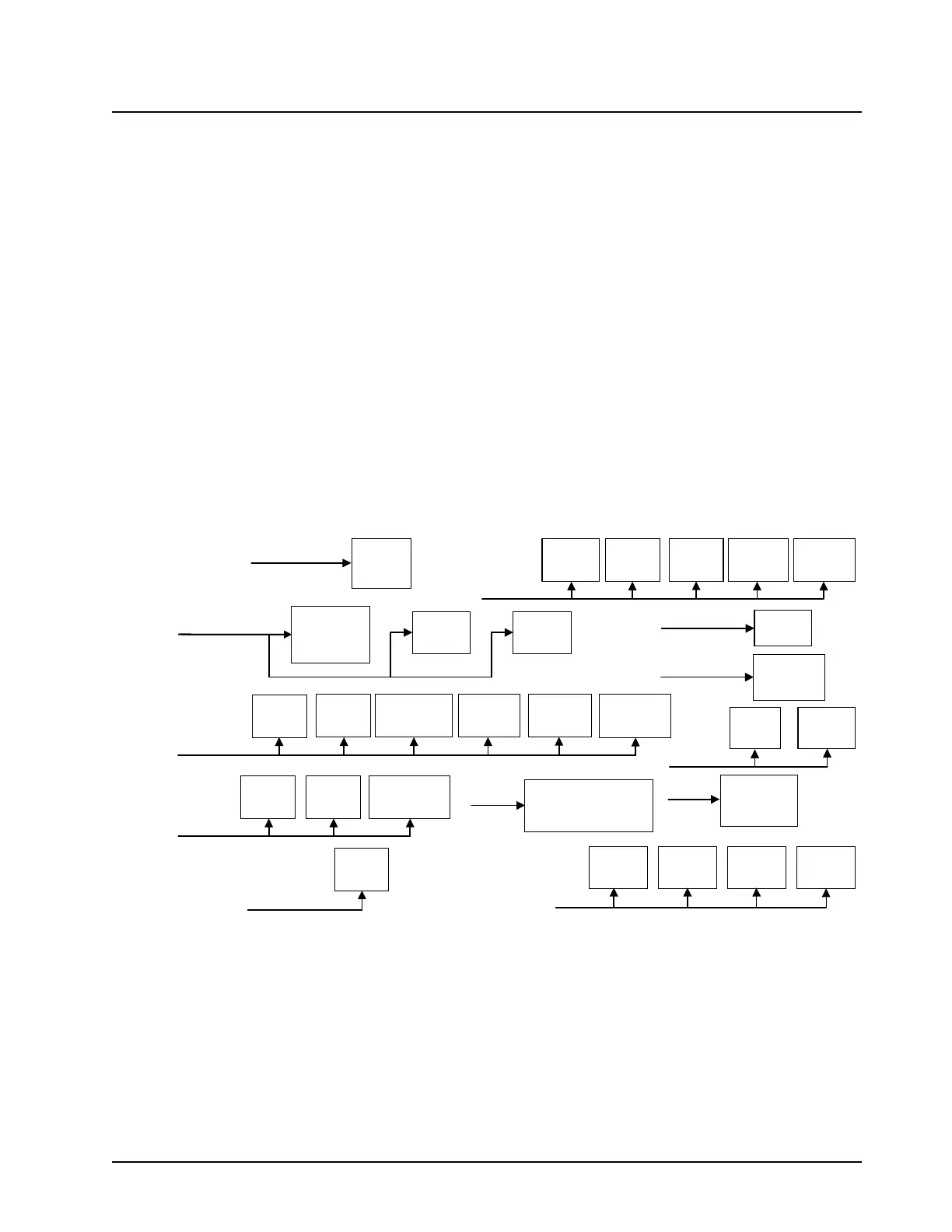
3.14.2 Controller DC Power Distribution
Figure 3-44 illustrates the controller DC power distribution circuitry.
The A+ power for the radio is derived from the 12-V battery, which is applied to the main board
through connector J0950. This A+ voltage is routed to the control-head connector, J0401, pins 19
and 21, to the control head.
A power FET (Q51) provides the means of controlling the main power source (SWB+) by the on/off
switch. SWB+ is routed back to the main board through connector J0401-17 and out the rear
connector, J2-24.
SW_B+ turns on controller FET switch Q0503, which supplies SW_A+ to regulator U0500. This 9.3-
V regulator powers up the main 5-V controller regulator U0503. The 5-V supply powers on all four
controller regulators:
• U0962 (3.0 V) for the power control section
• U0503 (2.85 V) for the controller and daughtercard I/O
• U0507 (1.85 V) for the memory
• U0502 (1.55 V) for the microprocessor core.
The SW+5-V regulator is the main power source for the controller.
Figure 3-44. B+ Routing for Controller Section
On the secure interface board, U800, Q802, and Q803 provide SWB+ to the encryption module (if
equipped). The SWB+ and UNSWB+ encryption voltages both originate from the secure interface
board and are fed to the encryption module via J0701 and J0501.
It should also be noted that a system reset is provided by the undervoltage detector, U0504. This
device brings the system out of reset on power-up, and provides a system reset to the
microcomputer on power-down.
3V, 2.8V,
1.8V, 1.5V
Regulators
PATRIOT
CORE
U100
PATRIOT
EIM
U100
8MB
FLASH
U102
IMB
SRAM
U103
VIP’s
SB9600
Circuit
RS232
Transceiver
U0305
Audio PA
Digital POT
U0206
5V
Regulator
U0503
FET (Q0952),
Power Ctrl
Loop
VCO
RX/FGU
5V Reg
9V
Regulators
U0950, U0951
U0500
Rear Acc’y Conn
(J2/J0402), Radio Turn
On/Off (Q0503 circuit),
Secure IF Board (J0501)
Audio PA
U0204
Control
Head
Secure IF
Board
J0500
SW_A+
FET
Q0503
A+
SW_A+
SW_B+
9.3V - FGU
9.3V - Controller
9.3V - TX
Unsw 5V = 5.0V
Vcc = 3.0V
Vcc2.8 = 2.85V
Vcc1.8 = 1.85V
Vcc1.5 = 1.55V
Vcc5 = 5.0V
ADC
U0953
EMERG
Timer
U0506
Secure IF
Board
J0500
USB
XCVR
U0304
Mic Amp Ckt
U0201, U0202,
Codec-U0200
Patriot I/O
SSI, SPI,
BBP, UARTs
U100
Misc. gates,
buffers, etc.
Modulation
DAC-U0900,
Urchin-U0901
DAC
U0959
Power Control
Digital POT
U0952
MAEPF-27892-O

 Loading...


