6815854H01-A June 15, 2005
Theory of Operation: Controller Section 3-75
3.14.11Flash Programming
When the radio needs new program code, this can often be done by reflashing the FLASH ROM
(U102) located on the daughtercard and the FLASH ROM (U1300) located on the control head.
Reflashing is accomplished by using a programming cable (HKN6183) and the Motorola Customer
Programming Software (CPS) FLASHport tool. The technique to flash the radio is the same as when
using CPS or the TUNER software to change features on your radio. The software will first flash the
codes into the U102 FLASH ROM and then proceed to U1300 FLASH ROM.
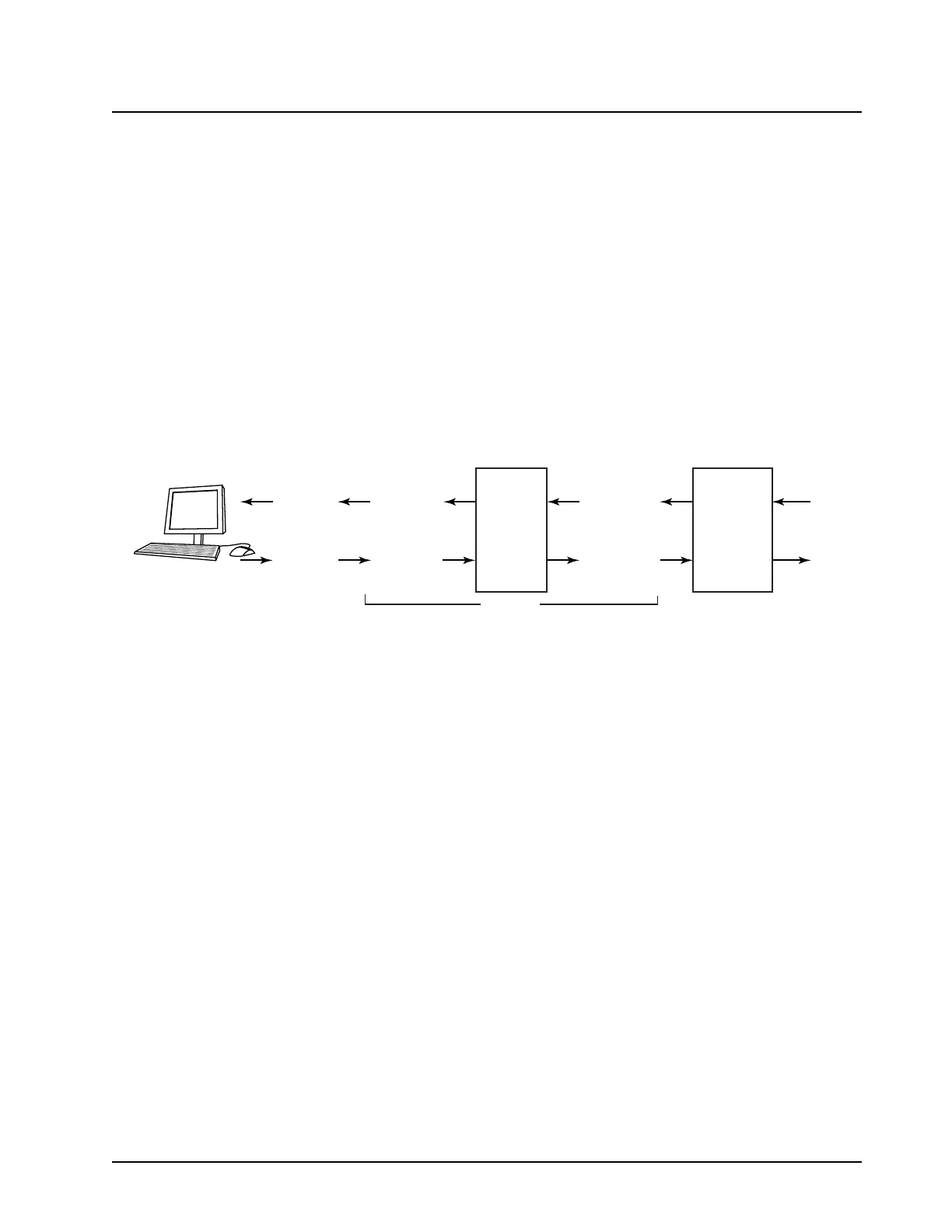
Two data lines are utilized on the programming cable to allow the computer to communicate with the
microcontroller. These two lines are called USB_DP_UART_TX (J7000-8) and USB_DM_UART_RX
(J7000-4) on the control head GCAI connector (see Figure 3-50).
The standard method of upgrading a radio's software and communicating between a computer and
the radio microcontroller involves the use of the UART path via the programming cable. The UART
lines from the GCAI connector connects to the OMAP applications processor in the control head in
which the data will be routed to the transceiver patriot IC via SSI link.
Figure 3-50. Boot RX and Boot TX Data Lines
The programming cable is detected by grounding GP1O_0 on the GCAI connector and in turn the
processor reads the one-wire memory in the same attached cable. If it determines from one-wire that
a two-wire RS232 cable is attached, RS232 on GCAI is enabled. This would enable the computer to
communicate with the OMAP applications processor and via SSI link allows the programming of the
transceiver radio.
Computer
(male) pin 2
(RX_DTE)
Computer
(male) pin 3
(TX_DTE)
9 pin cable
(female) pin 2
(TX_DCE)
9 pin cable
(female) pin 3
(RX_DCE)
Tout
14
13
Rin
Tin
11
12
Rout
RS232 IC
10 pin cable
(male) pin 8
(TX_DCE)
10 pin cable
(male) pin 4
(RX_DCE)
Controlhead
GCAI
Accessory
Connector
(J7000)
UART_TX
UART_RX
MAEPF-27815-O
HKN6183

 Loading...


