June 15, 2005 6815854H01-A
3-16 Theory of Operation: Receiver Front-End
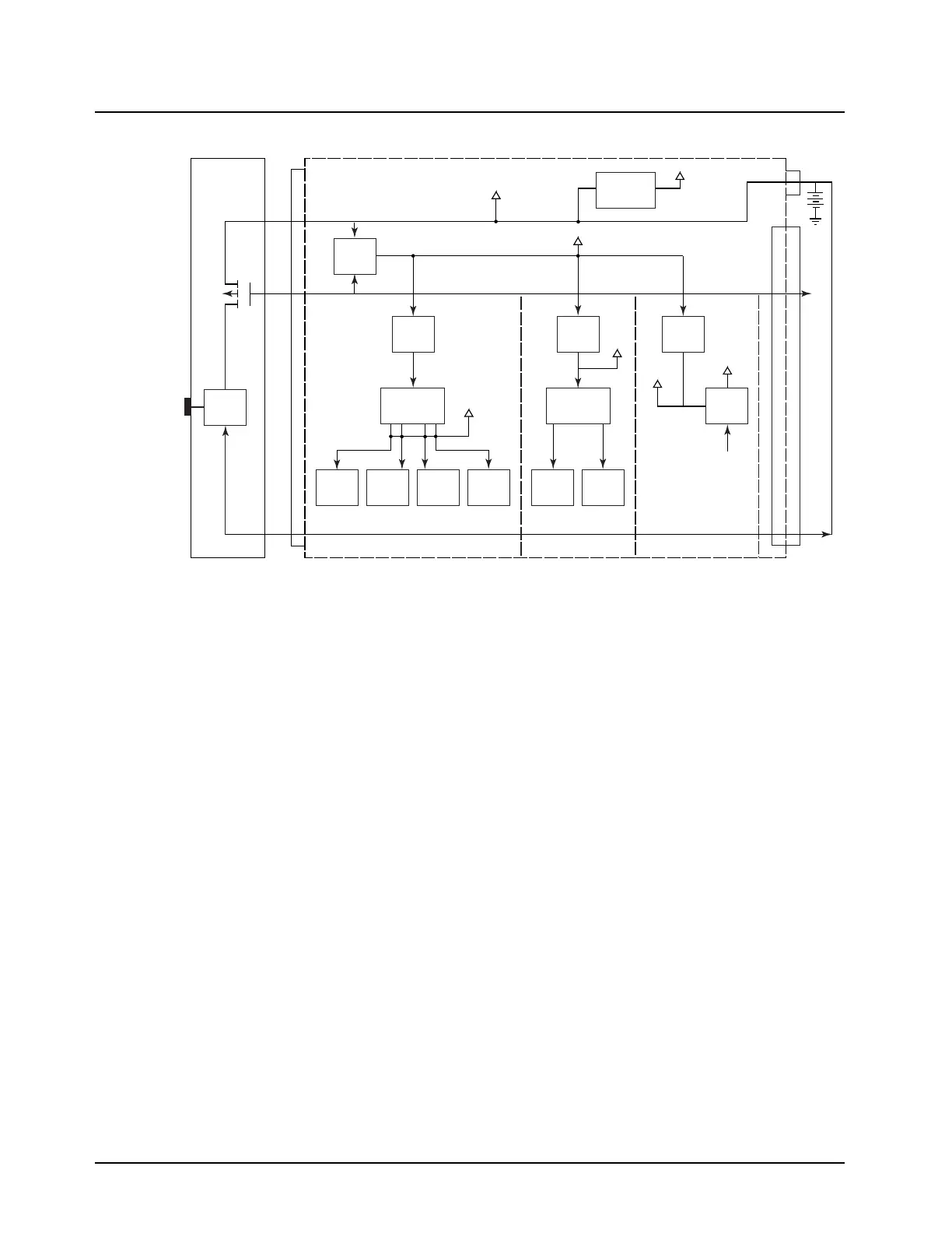
Figure 3-13. DC Voltage Routing Block Diagram (VHF and 700–800 MHz)
The 9.3 V and the A+ voltage are the main DC power for the RF section. The 9.1 V (referred to as
“keyed 9.1 V”) is controlled by the VOCON board through P501, pin 45. This DC voltage enables the
transmitter’s RF power amplifier when the VOCON board senses a lock detect from the synthesizer.
3.10 Receiver Front-End
This section provides a detailed circuit description of receiver front-end (RXFE). When reading the
Theory of Operation, refer to your appropriate schematic and component location diagrams located
in “Chapter 7. Schematics, Component Location Diagrams, and Parts Lists”. This detailed theory of
operation will help isolate the problem to a particular component.
3.10.1 VHF (136–174 MHz) Band
The receiver circuits primary duties are to detect, filter, amplify, and demodulate RF signals in the
presence of strong interfering noise and unintended signals. The receiver is broken down into the
following blocks (Figure 3-14 on page 3-17):
• Front-end, which includes:
- 15 dB step attenuator
- PIN diode switches
- Three discrete filters
- Two low-noise amplifiers
-Mixer
• Back-end, which includes:
- Two crystal filters
VCC5
9.3V_FGU
9.3V_TX
GPIO
KEYED_9.1_EN
A+
SW_A+
UWW_5V
On/Off
Controller Section
RX / FGU Section
Control Head
TX Section
J0401
A+
19, 21
SWB+
17
IGN
20
18
25
20, 22
24
SWB+
J0402
J2
J0950
9.3V
Regulator
U0500
9.33V
Regulator
U0950
9.3V
Regulator
U0951
Switch
3.0V
Regulator
U0962
2.85V
Regulator
U0501
1.85V
Regulator
U0507
1.55V
Regulator
U0502
3V
Regulator
U6002
3V
Regulator
U6750
FET
Q0503
UNSW
5V Circuit
VR0500, R0507
ATTiny13
5V
Regulator
U0503
5V
Regulator
U0505
MAEPF-27825-O

 Loading...


