6815854H01-A June 15, 2005
Troubleshooting Charts: Flowcharts 5-55
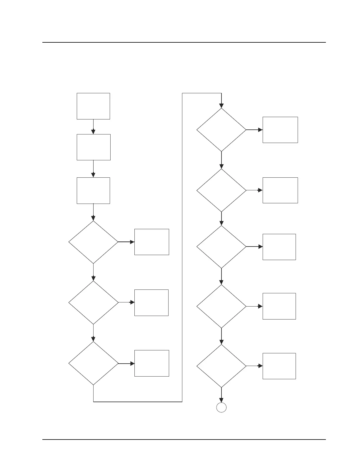
5.6.44 RF Power Amplifier (RFPA)—No or Low TX Power Output (700–800 MHz)—
Part 1 of 5
NOTE: For each flowchart step in which reference is made to a note, be sure to refer to that specific
note (located on page 58 of this flowchart) for guidance in performing the actual
troubleshooting procedure. Also, RFPA DC voltages are shown in Table 5-7 on page 5-59.
Figure 5-44. RF Power Amplifier (RFPA)—No or Low TX Power Output (700–800 MHz)—Part 1 of 5
Read General
Notes before
proceeding. Read
specific notes as
indicated
Check battery
cable, mic, and
control head
connections
START
Continuous red light
while mic button is
depressed?
GOTO Sythesizer-
No Transmit
Chart ?
Tune power with
Tuner?
(see help text)
No
Yes
Tune current limit
with Tuner
(see help text)
Yes
No
TX injection power
less than 2 mW?
(Note 1)
GOTO Sythesizer-
No or Low Tx
Injection
Chart ?
Yes
K9.1V
present
at Q0952, pin 1 in
power control section
when transmitter is
keyed?
No
GOTO Power
Control - No K9.1V
Chart ?
RFPA_CNTRL
voltage (VN_B6503)
less than 5.0V when
transmitter is
keyed?
Yes
No
GOTO Power
Control - No or low
RFPA_CNTRL
Chart ?
No
U6500 drain biases
voltages per Table 1?
(Note 3)
Yes
No
Check/repair/
replace defective
parts
Yes
No
A
Is U6500,
VCNTRL resistance <
1 kOhms?
(Note 2)
Yes
Repair/replace
U6500
No
Is U6500,
RFOUT and VD1
resistance <
1 MOhms?
(Note 4)
Yes
Repair/replace
U6500
MAEPF-27929-O

 Loading...


